Mitsubishi 380. Manual - part 328


  Index      Mitsubishi     Mitsubishi 380 - service repair manual 2005 year


Search            


Content   ..  326  327  328  329   ..


Mitsubishi 380. Manual - part 328


TRACTION CONTROL SYSTEM (TCL) DIAGNOSIS

TRACTION CONTROL SYSTEM (TCL)

13C-32

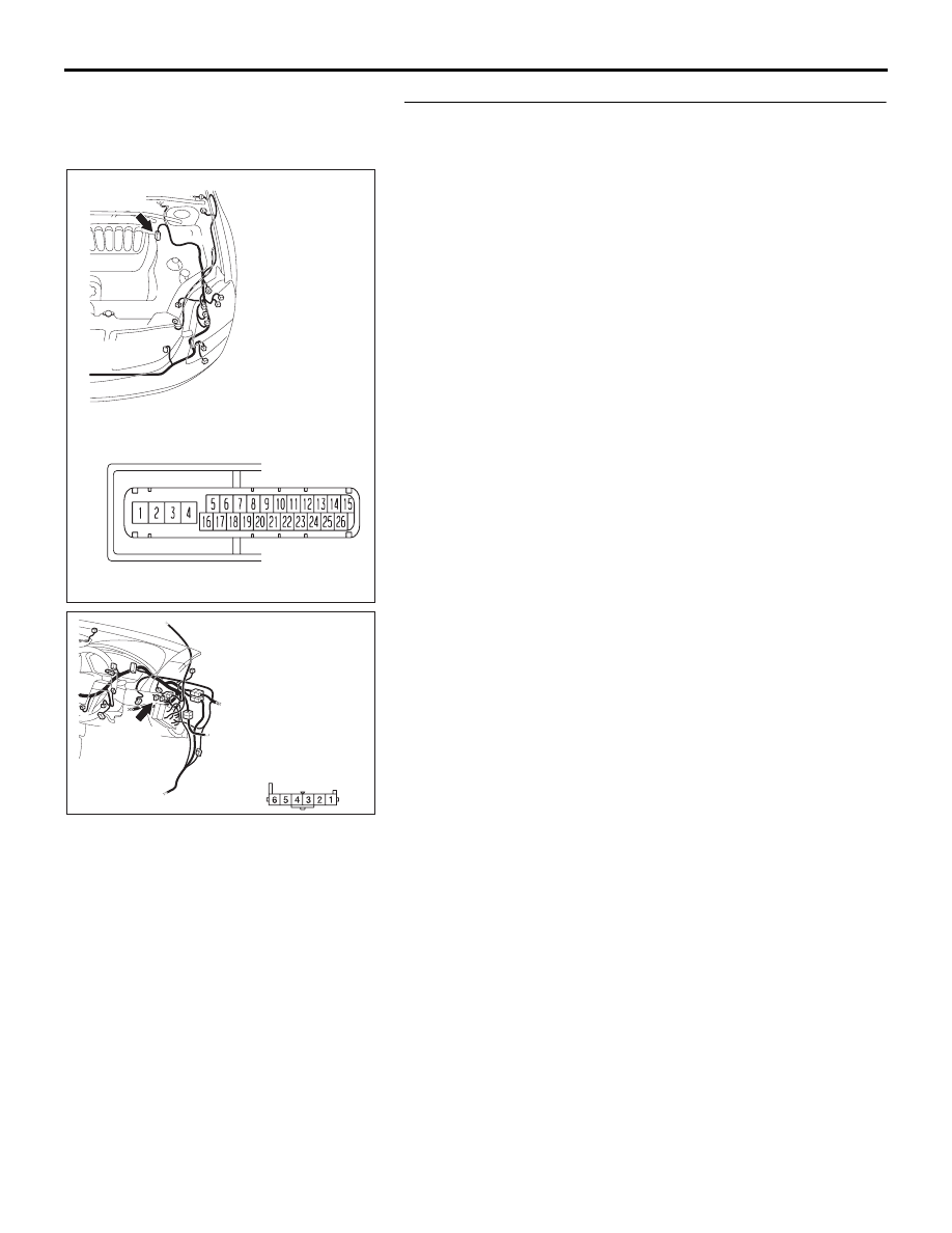
STEP 4. Check the harness wire between ABS/TCL-ECU 
connector A-02 terminal 21 and TCL switch connector 
C-131 terminal 1 for damage.
Q: Are there harness wires in good condition?

YES : Go to Step 5.
NO :  Repair the damaged harness wire. Then go to Step 7.

16DB402A

A-02 (GR)

CONNECTOR: A-02 

A-02 HARNESS CONNECTOR:

35DB116A

CONNECTOR: C-131

C-131(GR)

C-131 HARNESS

CONNECTOR:

COMPONENT SIDE

TRACTION CONTROL SYSTEM (TCL) DIAGNOSIS

TRACTION CONTROL SYSTEM (TCL)

13C-33

STEP 5. Check the harness wire between TCL switch 
connector C-131 terminal 2 and ground for damage.
Q: Is the harness wire in good condition?

YES : Go to Step 6.
NO :  Repair the damaged harness wire. Then go to Step 7.

STEP 6. Retest the system

Q: Does TCL system cancel, when the TCL switch is 

pushed on?
YES : 
It can be assumed that this malfunction is intermittent. 

(Refer to GROUP 00, How to Use 
Troubleshooting/Inspection Service Points 

− How to 

Cope with Intermittent Malfunction 

P.00-14

).

NO :  Replace the hydraulic unit (integrated with 

ABS/TCL-ECU). (Refer to GROUP 35B 

− Hydraulic 

Unit 

P.35B-93

). Then go to Step 7.

STEP 7. Retest the system

Q: Does TCL system cancel, when the TCL switch is 

pushed on?
YES : 
The procedure is complete.
NO :  Return to Step 1.

35DB117A

GROUND
TERMINAL

COMBINATION METER
CONNECTOR

35DB116A

CONNECTOR: C-131

C-131(GR)

C-131 HARNESS

CONNECTOR:

COMPONENT SIDE

TRACTION CONTROL SYSTEM (TCL) DIAGNOSIS

TRACTION CONTROL SYSTEM (TCL)

13C-34

INSPECTION PROCEDURE 6: TCL does not Operate.

NOTE: If the ABS-8 ECU or the active wheel 
speed sensor are disconnected, or if the wiring is 
an open/ short circuit, the ABS 8 ECU will shut 
off power supply to the respective wheel speed 
sensor. All other wheel speed sensors will oper-
ate normally. To restore the power supply, the 
ignition switch must be turned to the "OFF" posi-
tion then to the "ON" position again.

.

COMMENT

The fail-safe function is probably cancelling TCL. In 
this case, diagnostic tool MB991958 can be used to 
retest each system by checking the diagnostic trou-
ble codes.

.

TROUBLESHOOTING HINTS (THE MOST 
LIKELY CAUSES FOR THIS CASE:)

• Malfunction of the CAN bus line.

• Malfunction of the MPI system.

• Malfunction of the A/T system.

• Malfunction of the ABS/TCL-ECU.

DIAGNOSIS

Required Special Tools:

• MB991958: Diagnostic Tool (MUT-III Sub Assembly)

• MB991824: V.C.I.

• MB991827: MUT-III USB Cable

• MB991910: MUT-III Main Harness A

STEP 1. Using diagnostic tool MB991958, read the 
diagnostic trouble code.

CAUTION

To prevent damage to diagnostic tool MB991958, always 
turn the ignition switch to the "LOCK" (OFF) position 
before connecting or disconnecting diagnostic tool 
MB991958.
(1) Connect diagnostic tool MB991958 to the data link 

connector. (Refer to 

P.13C-3

).

(2) Turn the ignition switch to the "ON" position.
(3) Use diagnostic tool MB991958 to read the TCL diagnostic 

trouble codes. (Refer to 

P.13C-3

).

(4) Turn the ignition switch to the "LOCK" (OFF) position.
(5) Disconnect diagnostic tool MB991958.

Q: Is any DTC set?

YES : Repair the TCL. (Refer to 

P.13C-8

, Diagnostic 

Trouble Code Chart). Then go to Step 4.

NO :  Go to Step 2.

00DB076A

MB991910

DATA LINK

CONNECTOR

MB991824

MB991827

TRACTION CONTROL SYSTEM (TCL) DIAGNOSIS

TRACTION CONTROL SYSTEM (TCL)

13C-35

STEP 2. Using diagnostic tool MB991958, check TCL 
actuator test item09: Engine TCL Drive.

CAUTION

To prevent damage to diagnostic tool MB991958, always 
turn the ignition switch to the "LOCK" (OFF) position 
before connecting or disconnecting diagnostic tool 
MB991958.
(1) Connect diagnostic tool MB991958 to the data link 

connector. (Refer to 

P.13C-3

).

(2) Turn the ignition switch to the "ON" position.

CAUTION

The engine speed increases after the actuator test 
because the actuator test continues for only three sec-
onds. Therefore, release the accelerator pedal immedi-
ately. 
(3) Use diagnostic tool MB991958 to check the actuator test. 

(Refer to 

P.13C-3

).

• Item 09: Engine TCL Drive.

• When the accelerator pedal is depressed at the 

same time that the button for actuator test item 09 
displayed on diagnostic tool MB991958 is pressed, 
the system prevents the engine speed from rising for 
three seconds.

(4) Turn the ignition switch to the "LOCK" (OFF) position.
(5) Disconnect diagnostic tool MB991958.

Q: Are the check results for actuator test item 09 

satisfactory?
YES : 
Go to Step 3.
NO :  Replace the hydraulic unit (integrated with 

ABS/TCL-ECU). (Refer to GROUP 35B 

− Hydraulic 

Unit 

P.35B-93

). Then go to Step 4.

STEP 3. Retest the system

Q: Does the TCL work normally?

YES : It can be assumed that this malfunction is intermittent. 

(Refer to GROUP 00, How to Use 
Troubleshooting/Inspection Service Points 

− How to 

Cope with Intermittent Malfunction 

P.00-14

).

NO :  Replace the hydraulic unit (integrated with 

ABS/TCL-ECU). (Refer to GROUP 35B 

− Hydraulic 

Unit 

P.35B-93

). Then go to Step 4.

STEP 4. Retest the system

Q: Does the TCL work normally?

YES : The procedure is complete.
NO :  Return to Step 1.

00DB076A

MB991910

DATA LINK

CONNECTOR

MB991824

MB991827


Content   ..  326  327  328  329   ..