Mitsubishi 380. Manual - part 318


  Index      Mitsubishi     Mitsubishi 380 - service repair manual 2005 year


Search            


Content   ..  316  317  318  319   ..


Mitsubishi 380. Manual - part 318


MAINTENANCE SERVICE

GENERAL

00-50

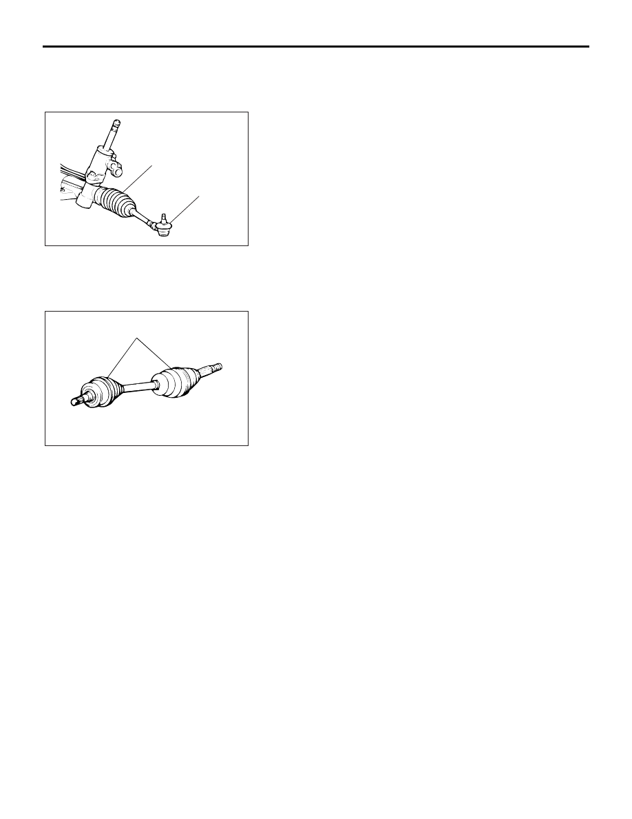
16. BALL JOINT AND STEERING LINKAGE 
SEALS (INSPECT FOR GREASE LEAKS AND 
DAMAGE)

M1001003500322

1. These components, which are permanently lubricated at the 

factory, do not require periodic lubrication. Damaged seals 
and boots should be replaced to prevent leakage or grease 
contamination.

2. Inspect the dust cover and boots for proper sealing, leakage 

and damage, and replace them if defective.

17. DRIVE SHAFT BOOTS (INSPECT FOR 
GREASE LEAKS AND DAMAGE)

M1001003600318

1. These components, which are permanently lubricated at the 

factory, do not require periodic lubrication. Damaged seals 
and boots should be replaced to prevent leakage or grease 
contamination.

2. Inspect the dust cover and boots for proper sealing, leakage 

and damage. Replace them if defective.

AC100948

BOOT

DUST

COVER

AB

AC000109 AB

BOOTS

MAINTENANCE SERVICE

GENERAL

00-51

18. SUSPENSION SYSTEM (INSPECT FOR 
LOOSENESS AND DAMAGE)

M1001009600048

Visually inspect the front/rear suspension components for dete-
rioration and damage. Re-tighten the front/rear suspension 
components retaining bolts to specified torque.

19. SRS AIR BAG (INSPECT FOR SRS SYSTEM)

M1001003700326

The entire SRS including air bag and pre-tensioner seat belt 
must be inspected by an authorized MITSUBISHI MOTORS 
dealer 10 years.

SRS WARNING LIGHT CHECK

Turn the ignition key to the "ON" position. Does the 

"SRS" warning light illuminate for several seconds, and then go 
out? If yes, the SRS system is functioning properly. If no, refer 
to GROUP 52B, Diagnosis 

P.52B-215

.

SRS COMPONENT VISUAL CHECK

DANGER

Wait at least 60 seconds after disconnecting the bat-
tery cable before doing any further work. The SRS 
system is designed to retain enough voltage to 
deploy the air bag for a short time even after the bat-
tery has been disconnected. Serious injury may result 
from unintended air bag deployment if work is done 
on the SRS system immediately after the battery 
cable is disconnected.

WARNING

Battery posts, terminals and related accessories con-
tain lead and lead compounds. WASH HANDS AFTER 
HANDLING.

1. Turn the ignition switch to the "LOCK" (OFF) position, 

disconnect the negative battery cable and tape the terminal.

2. Remove the floor console assembly (Refer to GROUP 52A, 

Floor Console 

P.52A-10

).

3. Disconnect a connector from the SRS-ECU.

ACX00902AB

TAPE

BATTERY

BATTERY CABLE

MAINTENANCE SERVICE

GENERAL

00-52

FRONT IMPACT SENSORS

1. Check that the arrows on the sensors face toward the front 

of the vehicle.

WARNING

The SRS may not activate if a front impact sensor 
is not installed properly, which could result in seri-
ous injury or death to the vehicle's driver and pas-
senger.

If a dent, crack, deformation or rust is detected, 
replace with a new sensor.

2. Check the front side member and front impact sensor for 

deformation or rust.

3. Check the front impact sensor wiring harness for binding; 

Check the connector for damage; and check the terminals 
for deformation.
Replace the sensor and/or wiring harness if they fail the 
visual check (Refer to GROUP 52B, SRS Service 
Precautions 

P.52B-16

 and GROUP 52B, Front Impact 

Sensor 

P.52B-231

).

SIDE IMPACT SENSORS

WARNING

If the side impact sensor is not installed securely 
and correctly, the side-air bag may not operate 
normally.

If a dent, crack, deformation or rust is detected, 
replace with a new sensor.

1. Check the side impact sensor and bracket for dents, cracks 

or deformation. The side impact sensors are located inside 
the center pillars (LH/RH).

2. Check the connector for damage, and terminal for 

deformation.

3. Check that there is no bending or corrosion in the center 

pillars (LH/RH).
Replace the side impact sensor if it fails the visual check 
(Refer to GROUP 52B, Side Impact Sensor 

P.52B-247

).

NOTE: The illustration shows the left side impact sensor (RH). 
The position of the other side impact sensor (LH) is symmetri-
cal to this.

AC306331AB

FRONT IMPACT
SENSOR

HEADLIGHT (RH)

RADIATOR SUPPORT
PANEL

AC206185AC

FRONT SEAT BELT

RETRACTOR

SIDE

IMPACT

SENSOR

MAINTENANCE SERVICE

GENERAL

00-53

SRS AIR BAG CONTROL UNIT (SRS-ECU) 

WARNING

The SRS may not activate if the SRS-ECU is not 
installed properly, which could result in serious injury 
or death to the vehicle's driver and front passenger.

1. Check the SRS-ECU case for dents, cracks, deformation or 

rust.

2. Check the connector for damage, and check the terminals 

for deformation or rust.
Replace the SRS-ECU if it fails the visual checks above 
(Refer to GROUP 52B, SRS Air Bag Control Unit 

P.52B-234

).

AIR BAG MODULE, STEERING WHEEL AND 
CLOCK SPRING 

WARNING

The removed air bag module should be stored in a 
clean, dry place with the pad cover face up.

Replace any visually inspected part if it fails the 
following inspection.

1. Remove the air bag module, steering wheel and clock 

spring.
(Refer to GROUP 52B, Air Bag Module and Clock Spring 

P.52B-237

).

2. Check the pad cover for dents, cracks or deformation.

24DB066A

SRS-ECU

CENTER

REINFORCEMENT

SRS-ECU

D-26    (Y),

C-121  (Y),

D-27    (Y)


Content   ..  316  317  318  319   ..