Mitsubishi 380. Manual - part 309


  Index      Mitsubishi     Mitsubishi 380 - service repair manual 2005 year


Search            


Content   ..  307  308  309  310   ..


Mitsubishi 380. Manual - part 309


HOW TO USE TROUBLESHOOTING/INSPECTION SERVICE POINTS

GENERAL

00-14

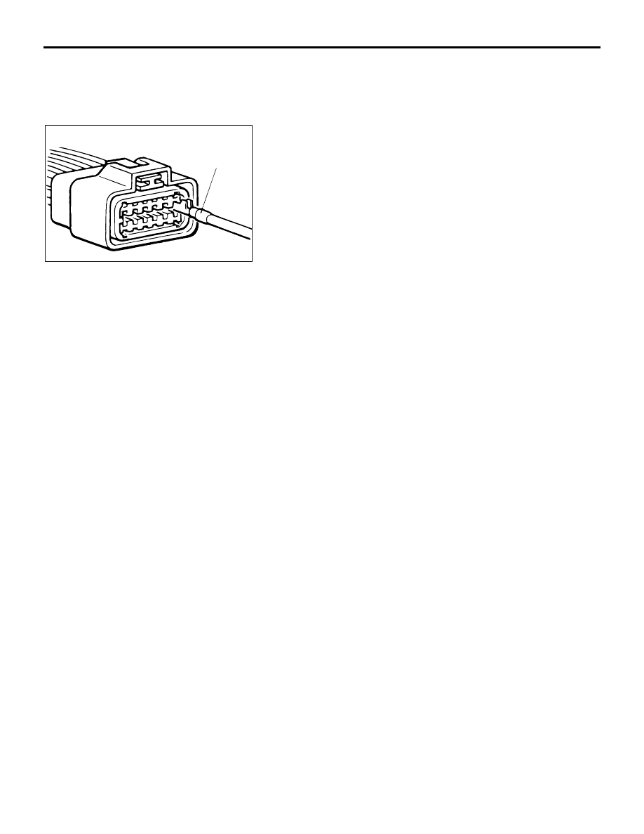
CONNECTOR ENGAGEMENT INSPECTION

Required Special Tool:

• MB991219: Inspection Harness (contained in MB991223 

Test Harness)

Use special tool MB991219 to inspect the engagement of the 
male pins and female pins. [Pin drawing force: 1 N (0.2 pound) 
or more]

HOW TO COPE WITH INTERMITTENT 
MALFUNCTIONS

M1001013900064

Most intermittent malfunctions occur under certain conditions. If 
those conditions can be identified, the cause will be easier to 
find.

.

TO COPE WITH INTERMITTENT MALFUNCTION;
1. ASK THE CUSTOMER ABOUT THE 
MALFUNCTION

Ask what it feels like, what it sounds like, etc. Then ask about 
driving conditions, weather, frequency of occurrence, and so 
on.

.

2. DETERMINE THE CONDITIONS FROM THE 
CUSTOMER'S RESPONSES

Typically, almost all intermittent malfunctions occur from condi-
tions like vibration, temperature and/or moisture change, poor 
connections. From the customer's responses, it should be rea-
soned which condition is most likely.

.

3. USE SIMULATION TEST

Use the simulation tests below to attempt to duplicate the cus-
tomer's complaint. Determine the most likely circuit(s) and per-
form the simulation tests on the connectors and parts of that 
circuit(s). Be sure to use the inspection procedures provided for 
diagnostic trouble codes and trouble symptoms.
For temperature and/or moisture condition related intermittent 
malfunctions, try to change the conditions of the suspected cir-
cuit components, then use the simulation tests below.

.

ACX00870 AB

MB991219

HOW TO USE TROUBLESHOOTING/INSPECTION SERVICE POINTS

GENERAL

00-15

4. VERIFY THE INTERMITTENT MALFUNCTION IS 
ELIMINATED

Repair the malfunctioning part and try to duplicate the condi-
tion(s) again to verify the intermittent malfunction has been 
eliminated.

.

SIMULATION TESTS

NOTE: In case of difficulty in finding the cause of the intermit-
tent malfunction, the data recorder function in the 
DIAGNOSTIC TOOL (MUT-III) is effective.
For these simulation tests, shake, then gently bend, pull, and 
twist the wiring of each of these examples to duplicate the inter-
mittent malfunction.

• Shake the connector up-and-down, and right-and-left.

• Shake the wiring harness up-and-down, and right-and-left. 

Especially, check the splice points of wiring harnesses care-
fully. Refer to GROUP 00E, Harness Connector Inspection 

P.00E-2

.

• Shake the part or sensor.

ACX00871 AB

HOW TO USE TROUBLESHOOTING/INSPECTION SERVICE POINTS

GENERAL

00-16

INSPECTION SERVICE POINTS FOR A BLOWN 
FUSE

M1001013800067

Remove the blown fuse and measure the resistance between 
the load side of the blown fuse and the ground. Close the 
switches of all circuits which are connected to this fuse. If the 
resistance is almost 0 

Ω at this time, there is a short some-

where between these switches and the load. If the resistance is 
not 0 

Ω, there is no short at the present time, but a momentary 

short has probably caused the fuse to blow.
The main causes of a short circuit are the following.

• Harness being clamped by the vehicle body

• Damage to the outer casing of the harness due to wear or 

heat

• Water getting into the connector or circuitry

• Human error (mistakenly shorting a circuit, etc).

HOW TO TREAT CURRENT TROUBLE

M1001014000020

1. Make a note of the diagnostic trouble code, and erase it.
2. Check the trouble symptom again.
3. Check for diagnostic trouble codes again.
4. If a diagnostic trouble code is set, follow the applicable 

Diagnostic Trouble Code Chart.

5. If no diagnostic trouble code is set, refer to "How to Cope 

with Intermittent Malfunction  

P.00-14

."

HOW TO TREAT PAST TROUBLE

M1001014100050

1. Establish from the customer whether a fuse or connector 

has been replaced or disconnected.

2. If yes, erase the diagnostic trouble code, and then check 

that no diagnostic code is reset. If no diagnostic trouble 
code is reset, the diagnosis is complete.

3. If no, follow the applicable Diagnostic Trouble Code Chart. 

Then check the wiring harness and connector, and refer to 
"How to Cope with Intermittent Malfunction 

P.00-14

."

ACX00872 AB

BATTERY

FUSE

LOAD

SWITCH

LOAD

SHORT-

CIRCUIT

OCCURRENCE

SECTION

AFFILIATED DTC REFERENCE TABLE

GENERAL

00-17

AFFILIATED DTC REFERENCE TABLE

M1001013000027

For vehicles with CAN, when DTC which influences 
the transmission data is set to the ECU which sends 
the data, DTC also could be set to the ECU which 
receives and controls the transmission data. The 
table below shows the relativity of DTC between 
ECUs.

AFFILIATED 
DTC’s

                                              RESULTS

   P0513

   P2138

   TBA

   U1120

   U1100

   U1110

       U1120

       X

       -

       X

       -

       -

       -

       U1100

       -

       -

       -

       -

       -

       -

       U1120

       X

       X

       X

       X

       -

       X

       U1110

       -

       -

       -

       -

       -

       -


 TBA

       -

       -

       -

       -

       -

       -


Content   ..  307  308  309  310   ..