Mitsubishi 380. Manual - part 265


  Index      Mitsubishi     Mitsubishi 380 - service repair manual 2005 year


Search            


Content   ..  263  264  265  266   ..


Mitsubishi 380. Manual - part 265


MARK

EXTERIOR

51-26

INSTALLATION SERVICE POINT

.

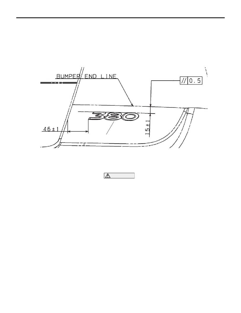
>>A<< MARK INSTALLATION

1. Installation position 

Attach the correct grade mark to the position shown in the 
illustration. ie (380/380LS/380VRX/380GT).

2. Installation procedure

(1) Use 3M

™ AAD Part number 8906 or equivalent to clean 

the mark installation surfaces on the body.

CAUTION

When attaching the mark, the ambient temperature should 
be 20 

 38°C (60  100°F) and the air should be completely 

free of dust. If the ambient temperature is lower than 20

°

(60

°F), the mark and the place on the vehicle body where 

the mark is to be attached should be heated to 20 

 38°

(60 

 100°F).

(2) Peel off the protection sheet on the back of the mark to 

affix it in position.

20DB115A

380 MARK

DOOR MIRROR

EXTERIOR

51-27

DOOR MIRROR

GENERAL DESCRIPTION

M1511000100570

OPERATION DOOR MIRROR

Remote Controlled Mirror Operation

• The mirror on the door mirror moves up/down 

and left/right by operating the remote controlled 
door mirror switch when the ignition switch is in 
the "ON" or "ACC" position.

DOOR MIRROR

EXTERIOR

51-28

DOOR MIRROR

REMOVAL AND INSTALLATION

M1511006400331

20DB106A

1

2

2

B

B

<FRONT DOOR>

3

NOTE

         : CLAW POSITIONS 

A

5.0 ± 1.0 N·m

44 ± 9 inlb

1

2

SECTION B – B

VIEW A

SECTION C – C

SECTION D – D

C

C

D

D

D

D

D

D

D

D

D

CLAW

CLAW

TRIM

TRIM

D

DOOR MIRROR

EXTERIOR

51-29

REMOVAL SERVICE POINT

.

<<A>> POWER WINDOW SWITCH PANEL 
ASSEMBLY REMOVAL

Insert special tool MB990874 as shown to remove the power 
window switch panel assembly.

INSPECTION

M1511006500305

ELECTRIC REMOTE CONTROL MIRROR 
OPERATION CHECK

Check that the mirror moves as described in the table when 
each terminal is connected to the battery.

REMOTE CONTROLLED MIRROR 
REMOVAL STEPS

FRONT DOOR TRIM (REFER TO 
GROUP 52A, DOOR TRIMS 

P.52A-14

).

1. DOOR MIRROR COVER
2. REMOTE CONTROLLED MIRROR 

ASSEMBLY

REMOTE CONTROLLED MIRROR 
SWITCH REMOVAL STEPS

<<A>>

3. POWER WINDOW SWITCH PANEL 

ASSEMBLY 

4. REMOTE CONTROLLED MIRROR 

SWITCH

20DB116A

MB990784

POWER WINDOW SWITCH 

PANEL ASSEMBLY

BATTERY CONNECTION

DIRECTION 
OPERATION

• Connect terminal 6 to the negative 

battery terminal.

• Connect terminal 4 to the positive battery 

terminal.

Up

• Connect terminal 6 to the positive battery 

terminal.

• Connect terminal 4 to the negative 

battery terminal.

Down

• Connect terminal 6 to the negative 

battery terminal.

• Connect terminal 5 to the positive battery 

terminal.

Right

• Connect terminal 6 to the positive battery 

terminal.

• Connect terminal 5 to the negative 

battery terminal.

Left

20DB117A


Content   ..  263  264  265  266   ..