Mitsubishi 380. Manual - part 235


  Index      Mitsubishi     Mitsubishi 380 - service repair manual 2005 year


Search            


Content   ..  233  234  235  236   ..


Mitsubishi 380. Manual - part 235


ENGINE COOLING DIAGNOSIS

ENGINE COOLING

14-24

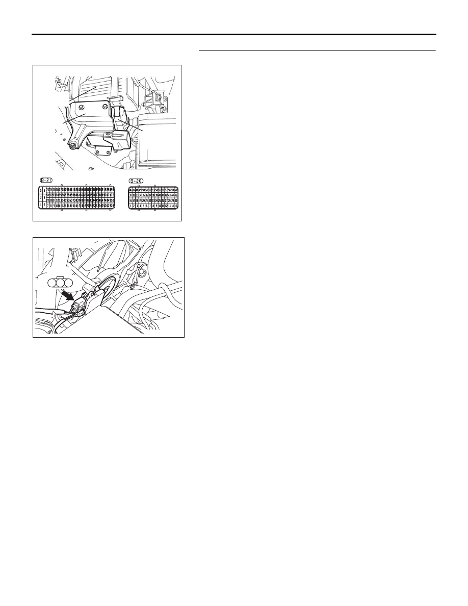
STEP 6. Check the fan controller.

(1) Disconnect fan controller connector A-24.

(2) Back out connector terminal pin 2 from connector housing.
(3) Reconnect the connector with connector terminal pin 2 still 

removed.

(4) Turn the ignition switch to the "ON" position.
(5) Check for the cooling fan operation.

• The cooling fan rotates. (with connector terminal pin 2 

disconnected)

(6) Check for the cooling fan operation.

• Using a suitable probe connect the fan controller termi-

nal 2 at controller side to earth.The cooling fan stops. 
(When pin 2 of fan controller is connected to earth)

(7) Turn the ignition switch to the "OFF" position.
(8) Disconnect fan controller connector A-24, and re-locate  

connector terminal pin 2 into connector housing.

(9) Reconnect the connector with connector terminal pin 2 

installed correctly.

Q: Does the cooling fan rotate? And when the fan 

controller pin 2  is connected to the body earth, does 
the cooling fan stop?
YES : 
Go to Step 7.
NO :  Replace the fan motor and fan controller (Refer to 

14-25

). Then go to Step 8.

16DB400A

COVER

ENGINE

CONTROL

UNIT

AIR

CLEANER

04DB008A

1

2

3

A-24

Connector: A-24

ENGINE COOLING DIAGNOSIS

ENGINE COOLING

14-25

STEP 7. MUT-III self-diag code
Check if an MPI system self-diag code is set. (Refer to GROUP 
13A - Trouble shootin

13A-5

)

Q: Diagnosis code set?

YES : Inspection chart for diagnosis code (Refer to GROUP 

13A - Trouble shootin

13A-5

)

NO :  Replace the engine-ECU (Refer to GROUP 13A, 

Engine-ECU 

13A-675

 ) Then go to Step 8 .

STEP 8. Check the symptoms.

Q: Does the radiator fan motor and the condenser fan 

motor operate correctly?
YES : 
This symptom is complete.
NO :  Return to Step 1.

INSPECTION PROCEDURE 5: Radiator Fan does not Operate

.

Radiator Fan and Condenser Fan Drive 
Circuit 

.

TECHNICAL DESCRIPTION

The cause could be a malfunction of the radiator fan 
motor or an open circuit between the fan controller 
and the radiator fan motor.

.

TROUBLESHOOTING HINTS

• Malfunction of radiator fan motor

• Malfunction of fan controller

• Refer to component locations GROUP-1

• Refer to configuration diagrams GROUP-1

• Refer to circuit diagrams GROUP-1

DIAGNOSIS

Replace the radiator fan motor and fan controller assembly.

Q: Does the radiator fan operate correctly?

YES : There is no action to be taken?
NO :  Repair the wiring harness between the fan controller 

and the radiator fan motor.

INSPECTION PROCEDURE 6: Condenser Fan does not Operate

.

Radiator Fan and Condenser Fan Drive 
Circuit   

.

TECHNICAL DESCRIPTION

The cause could be a malfunction of the condenser 
fan motor or fan controller.

.

TROUBLESHOOTING HINTS

• Malfunction of condenser fan motor

• Malfunction of fan controller

• Refer to component locations GROUP-1

• Refer to configuration diagrams GROUP-1

• Refer to circuit diagrams GROUP-1

ON-VEHICLE SERVICE

ENGINE COOLING

14-26

DIAGNOSIS

STEP 1. Check the condenser fan motor.
Condenser fan motor check. (Refer to GROUP 55, Condenser 
and Condenser Fan Motor.

Q: Is the condenser fan motor in good condition?

YES : Go to Step 2.
NO :  Replace the condenser fan motor, then go to Step 3.

STEP 2. Check the fan controller.
Refer to 29.

Q: Is the fan controller in good condition?

YES : Go to Step 3.
NO :  Replace the fan motor and fan controller (Refer to 

14-25

). Then go to Step 3.

STEP 3. Check the symptoms.

Q: Do the condenser fan operate?

YES : This symptom is complete.
NO :  Return to Step 1.

ON-VEHICLE SERVICE

ENGINE COOLANT LEAK CHECK

M1141001000333

WARNING

When pressure testing the cooling system, slowly 
release cooling system pressure to avoid getting 
burned by hot coolant.

CAUTION

• Be sure to completely clean away any moisture from 

the places checked.

• When the tester is taken out, be careful not to spill any 

coolant.

• Be careful when installing and removing the tester and 

when testing not to deform the filler neck of the radia-
tor.

1. Check that the coolant level is up to the filler neck. Install a 

radiator tester and apply 160 kPa (23 psi) pressure, and 
then check for leakage from the radiator hose or 
connections.

2. If there is leakage, repair or replace the appropriate part.

ACX01844 AB

CAP ADAPTER

ADAPTER

ON-VEHICLE SERVICE

ENGINE COOLING

14-27

RADIATOR CAP PRESSURE CHECK

M1141001300419

NOTE: Be sure that the cap is clean before testing. Rust or 
other foreign material on the cap seal will cause an improper 
reading.

1. Use a cap adapter to attach the cap to the tester.

2. Increase the pressure until the indicator of the gauge stops 

moving.

Minimum limit: 83 kPa (12 psi)
Standard value: 93 

 123 kPa (14  18 psi)

3. Replace the radiator cap if the reading does not remain at or 

above the limit.

ENGINE COOLANT REPLACEMENT

M1141001200478

WARNING

When removing the radiator cap, use care to avoid 
contact with hot coolant or steam. Place a shop towel 
over the cap and turn the cap counterclockwise a lit-
tle to let the pressure escape through the vinyl tube. 
After relieving the steam pressure, remove the cap by 
slowly turning it counterclockwise.

1. Drain the water from the radiator, heater core and engine 

after unplugging the radiator drain plug and removing the 
radiator cap.

ACX01845 AB

CAP ADAPTER


Content   ..  233  234  235  236   ..