Mitsubishi 380. Manual - part 183


  Index      Mitsubishi     Mitsubishi 380 - service repair manual 2005 year


Search            


Content   ..  181  182  183  184   ..


Mitsubishi 380. Manual - part 183


AUTO A/C DIAGNOSIS

HEATER, AIR CONDITIONING AND VENTILATION

55-28

DTC B1041, B1042: Air Mixing Damper Control Motor and Potentiometer (Potentiometer system)

.

DTC SET CONDITION

• DTC B1041 or B1042 is set if there is an open or 

short circuit in the potentiometer input circuit, or if 
there is an open circuit in the power circuit or 
earth circuit.

.

TECHNICAL DESCRIPTION (COMMENT)

Current trouble

• The A/C-ECU, the air mixing damper control 

motor and potentiometer, or connector(s) or wir-
ing between the two may be defective.

Past trouble

• If DTC B1041 or B1042 is stored as a past trou-

ble, carry out diagnosis with particular emphasis 
on wiring and connector(s) between the A/C-ECU 
and the air mixing damper control motor and 
potentiometer. If the connectors and wiring are 
normal, and obviously the ECU is the cause of 
the trouble, replace the ECU. If in doubt, do not 
replace the ECU.

TROUBLESHOOTING HINT

• Malfunction of connector.

• Malfunction of the harness.

• Malfunction of the air mixing damper control 

motor and potentiometer.

• Malfunction of the A/C-ECU.

• Refer to component locations GROUP-

70

• Refer to configuration diagrams GROUP-

80

• Refer to circuit diagrams GROUP-

90

DIAGNOSIS

Required Special Tool:

•  : Diagnostic Tool (MUT-III Sub Assembly)

• MB991824: Vehicle Communication Interface (V.C.I.)

• MB991827: MUT-III USB Cable

• MB991910: MUT-III Main Harness A (Vehicles with CAN 

communication system)
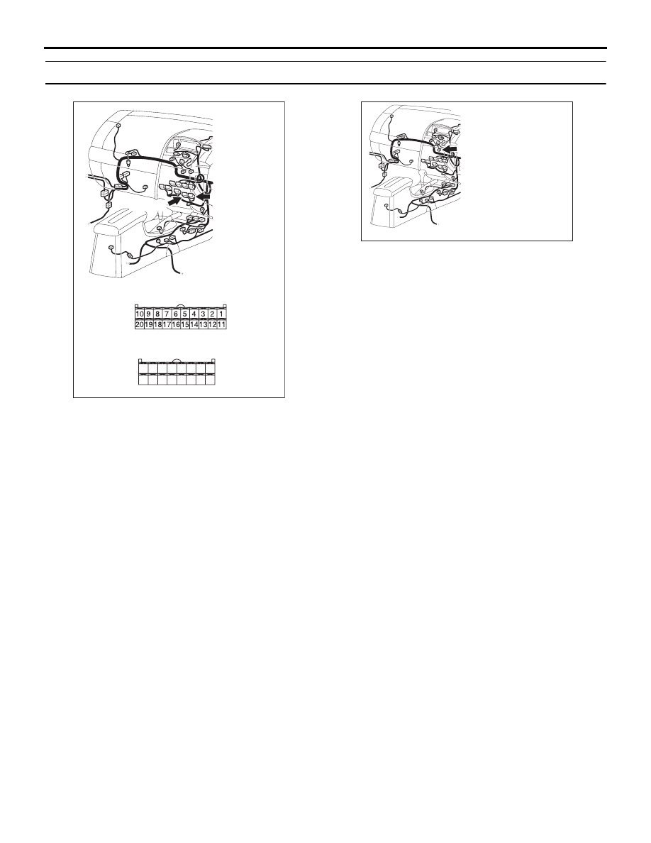
25DB070A

CONNECTORS: C-15, C-16

C-16 (B)

HARNESS SIDE

C-16

C-15

C-15 (B)

HARNESS SIDE

21

22

23

24

25

26

27

28

29

30

31

32

33

34

35

36

25DB083A

CONNECTOR: C-105

C-105

AUTO A/C DIAGNOSIS

HEATER, AIR CONDITIONING AND VENTILATION

55-29

STEP 1. Using diagnostic tool , diagnose the CAN bus line.
Use diagnostic tool  to diagnose the CAN bus lines.
(1) Connect diagnostic tool  to the data link connector.
(2) Turn the ignition switch to "ON" position.
(3) Diagnose the CAN bus line.

Q: Is the check result satisfactory?

YES : Go to Step 2.
NO :  Repair the CAN bus lines. (Refer to GROUP 54C, 

Diagnosis-Can Bus Diagnostic Chart 

P.54C-405

). 

Then go to Step 7.

STEP 2. Recheck for diagnostic trouble code.
Recheck if the DTC is set.
(1) Erase the DTC.
(2) Turn the ignition switch to "ON" position.
(3) Check if the DTC is set.

Q: Is the check result satisfactory?

YES : It can be assumed that this malfunction is intermittent. 

Refer to GROUP 00, How to Use 
Troubleshooting/Inspection Service Points 

− How to 

Cope with Intermittent Malfunctions 

P.00-14

.

NO :  Go to Step 3. 

00DB076A

MB991910

DATA LINK

CONNECTOR

MB991824

MB991827

AUTO A/C DIAGNOSIS

HEATER, AIR CONDITIONING AND VENTILATION

55-30

STEP 3. Using diagnostic tool , check data list item 63: Air 
mix potentiometer.

CAUTION

To prevent damage to diagnostic tool , always turn the 
ignition switch to the "LOCK" (OFF) position before con-
necting or disconnecting diagnostic tool .
(1) Connect diagnostic tool  to the data link connector.
(2) Start the engine.
(3) Set diagnostic tool  to the data reading mode for item 63: Air 

mix potentiometer.

• Check that the set position of the heater control matches 

the displayed position on the diagnostic tool.

(4) Turn the ignition switch to the "LOCK" (OFF) position.

Q: Is the sensor within the specified range?

YES : Replace the A/C-ECU. Then go to Step 7.
NO :  Go to Step 4.

00DB076A

MB991910

DATA LINK

CONNECTOR

MB991824

MB991827

AUTO A/C DIAGNOSIS

HEATER, AIR CONDITIONING AND VENTILATION

55-31

STEP 4. Check A/C-ECU connector C-15, C-16 and air 
mixing damper control motor and potentiometer connector 
C-105 for loose, corroded or damaged terminals, or 
terminals pushed back in the connector.
Q: Are A/C-ECU connector C-15, C-16 and air mixing 

damper control motor and potentiometer connector 
C-105 in good condition?
YES : 
Go to Step 5.
NO :  Repair or replace the connector. Refer to GROUP 

00E, Harness Connector Inspection 

P.00E-2

. Then g

to Step 7.

25DB084A

CONNECTOR: C-105

C-105

C-105

HARNESS SIDE

25DB070A

CONNECTORS: C-15, C-16

C-16 (B)

HARNESS SIDE

C-16

C-15

C-15 (B)

HARNESS SIDE

21

22

23

24

25

26

27

28

29

30

31

32

33

34

35

36


Content   ..  181  182  183  184   ..