Mitsubishi 380. Manual - part 182


  Index      Mitsubishi     Mitsubishi 380 - service repair manual 2005 year


Search            


Content   ..  180  181  182  183   ..


Mitsubishi 380. Manual - part 182


AUTO A/C DIAGNOSIS

HEATER, AIR CONDITIONING AND VENTILATION

55-24

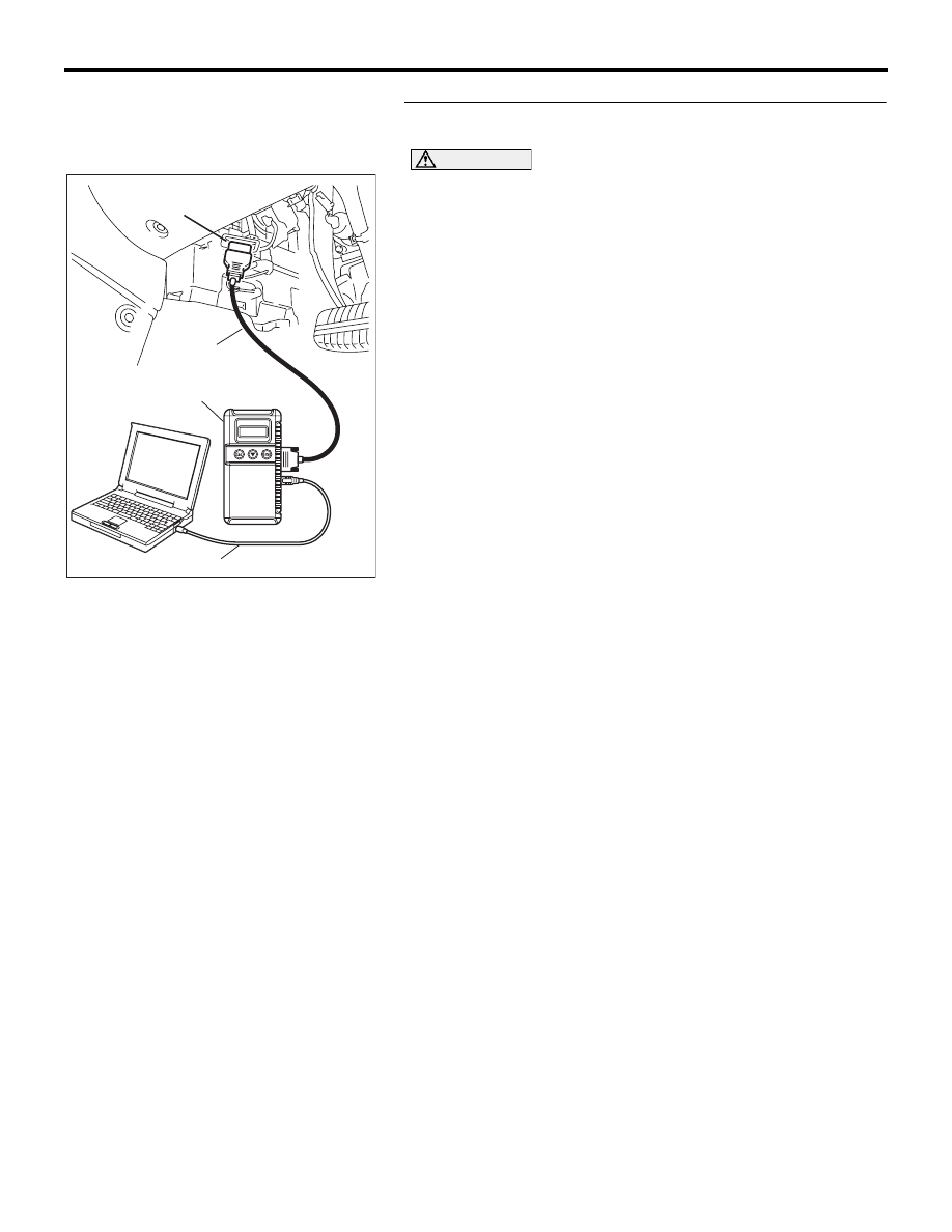
STEP 3. Using diagnostic tool , check data list item 20: Air 
thermo sensor.

CAUTION

To prevent damage to diagnostic tool , always turn the 
ignition switch to the "LOCK" (OFF) position before con-
necting or disconnecting diagnostic tool .
(1) Connect diagnostic tool  to the data link connector.
(2) Ignition switch: ON
(3) Set diagnostic tool  to the data reading mode for item 20: Air 

thermo sensor.

• Check that the passenger room temperature matches 

the displayed value on the diagnostic tool while the 
engine is cold.

NOTE: When this DTC is set and the system is fail-safe sta-
tus, the value of service data displays 

6°C.

(4) Turn the ignition switch to the "LOCK" (OFF) position.

Q: Is the sensor within the specified range?

YES : Replace the A/C-ECU. Then go to Step 7.
NO :  Go to Step 4.

00DB076A

MB991910

DATA LINK

CONNECTOR

MB991824

MB991827

AUTO A/C DIAGNOSIS

HEATER, AIR CONDITIONING AND VENTILATION

55-25

STEP 4. Check A/C-ECU connector C-15, C-16 and air 
thermo sensor connector C-126 for loose, corroded or 
damaged terminals, or terminals pushed back in the 
connector.
Q: Are A/C-ECU connector C-15, C-16 and air thermo 

sensor connector C-126 in good condition?
YES : 
Go to Step 5.
NO :  Repair or replace the connector. Refer to GROUP 

00E, Harness Connector Inspection 

P.00E-2

. Then g

to Step 7.

25DB080A

CONNECTOR: C-126

HARNESS SIDE

25DB070A

CONNECTORS: C-15, C-16

C-16 (B)

HARNESS SIDE

C-16

C-15

C-15 (B)

HARNESS SIDE

21

22

23

24

25

26

27

28

29

30

31

32

33

34

35

36

AUTO A/C DIAGNOSIS

HEATER, AIR CONDITIONING AND VENTILATION

55-26

STEP 5. Check the wiring harness between A/C-ECU 
connector C-15 (terminal 20), C-16 (terminal 24) and air 
thermo sensor connector C-126 (terminals 2 and 1).
Q: Is the wiring harness between A/C-ECU connector C-10 

(terminal 10 and 13) and air thermo sensor connector 
C-126 (terminals 2 and 1) in good condition?
YES : 
Go to Step 6.
NO :  Repair the wiring harness. Then go to Step 7.

25DB080A

CONNECTOR: C-126

HARNESS SIDE

25DB070A

CONNECTORS: C-15, C-16

C-16 (B)

HARNESS SIDE

C-16

C-15

C-15 (B)

HARNESS SIDE

21

22

23

24

25

26

27

28

29

30

31

32

33

34

35

36

AUTO A/C DIAGNOSIS

HEATER, AIR CONDITIONING AND VENTILATION

55-27

STEP 6. Check the air thermo sensor.
(1) Disconnect the air thermo sensor connector C-126.

(2) Measure the resistance between connector terminals 1 and 

2 under at least two different temperatures. The resistance 
values should generally match those in the graph. 

NOTE: The temperature at the check should not exceed the 
range in the graph. 

Q: Is the air thermo sensor in good condition?

YES : Replace the A/C-ECU. Then go to Step 7.
NO :  Replace the air thermo sensor. Then go to Step 7.

STEP 7. Recheck for diagnostic trouble code.
Check again if the DTC is set.
(1) Connect diagnostic tool  to the data link connector
(2) Turn the ignition switch to the "ON" position.
(3) Check if the DTC is set.
(4) Turn the ignition switch to the "LOCK" (OFF) position.

Q: Is the check result satisfactory?

YES : The procedure is complete.
NO :  Return to Step 1.

25DB080A

CONNECTOR: C-126

HARNESS SIDE

AC001043

RESISTANCE kΩ

8

6

4

2

0

-10

0

 10

 20

 30

   40

TEMPERATURE ˚C(˚F)

AB

(14)

(32)

(50)

(86) (104)

(68)

00DB076A

MB991910

DATA LINK

CONNECTOR

MB991824

MB991827


Content   ..  180  181  182  183   ..