Mitsubishi 380. Manual - part 146
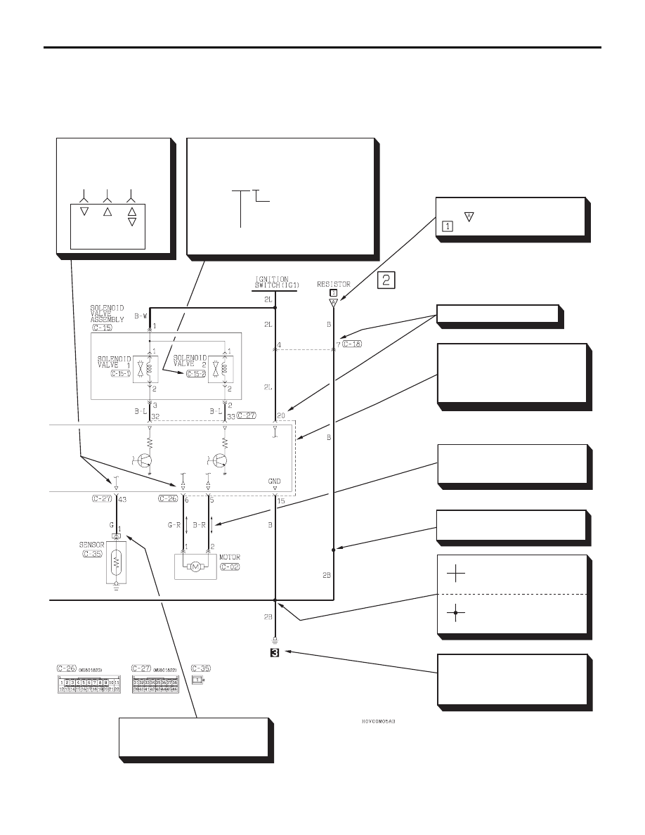
HOW TO READ CIRCUIT DIAGRAMS
CIRCUIT DIAGRAMS
90-4
36DB002A
Indicates representative vehicle
body ground point. (Same
number as that of ground point in
GROUNDING LOCATION).
Indicates harness junction where
wire diameter or color changes.
In case two or more connectors
are connected to the same de-
vice, markings indicating
the same connector is
connected by a broken line.
Indicates terminal number.
Indicates intersections at
which the lead wires are
not connected.
Indicates intersections at
which the lead wires are
connected.
Indicates input/output
to/from control unit
(current flow direction).
Input Output
Input/
output
Indicates that the diagram comes
from which belongs to the
block in the same circuit.
Indicates a wiring connector which is inside
the equipment and which is not shown in
the wiring harness configuration diagram.
Example C-15-2
Indicates a connector
which is inside the
equipment, numbered
in order starting from 1.
Indicates the connector number shown in
the wiring harness configuration diagram.
Bi-directional arrow indicates
that current flows in both direc-
tions due to control by an ECU.
Indicates that the terminal is a
spare one if the device (sensor
in this case) is not provided.