Mitsubishi 380. Manual - part 117


  Index      Mitsubishi     Mitsubishi 380 - service repair manual 2005 year


Search            


Content   ..  115  116  117  118   ..


Mitsubishi 380. Manual - part 117


INPUT SIGNAL PROCEDURES

SIMPLIFIED WIRING SYSTEM (SWS)

54B-465

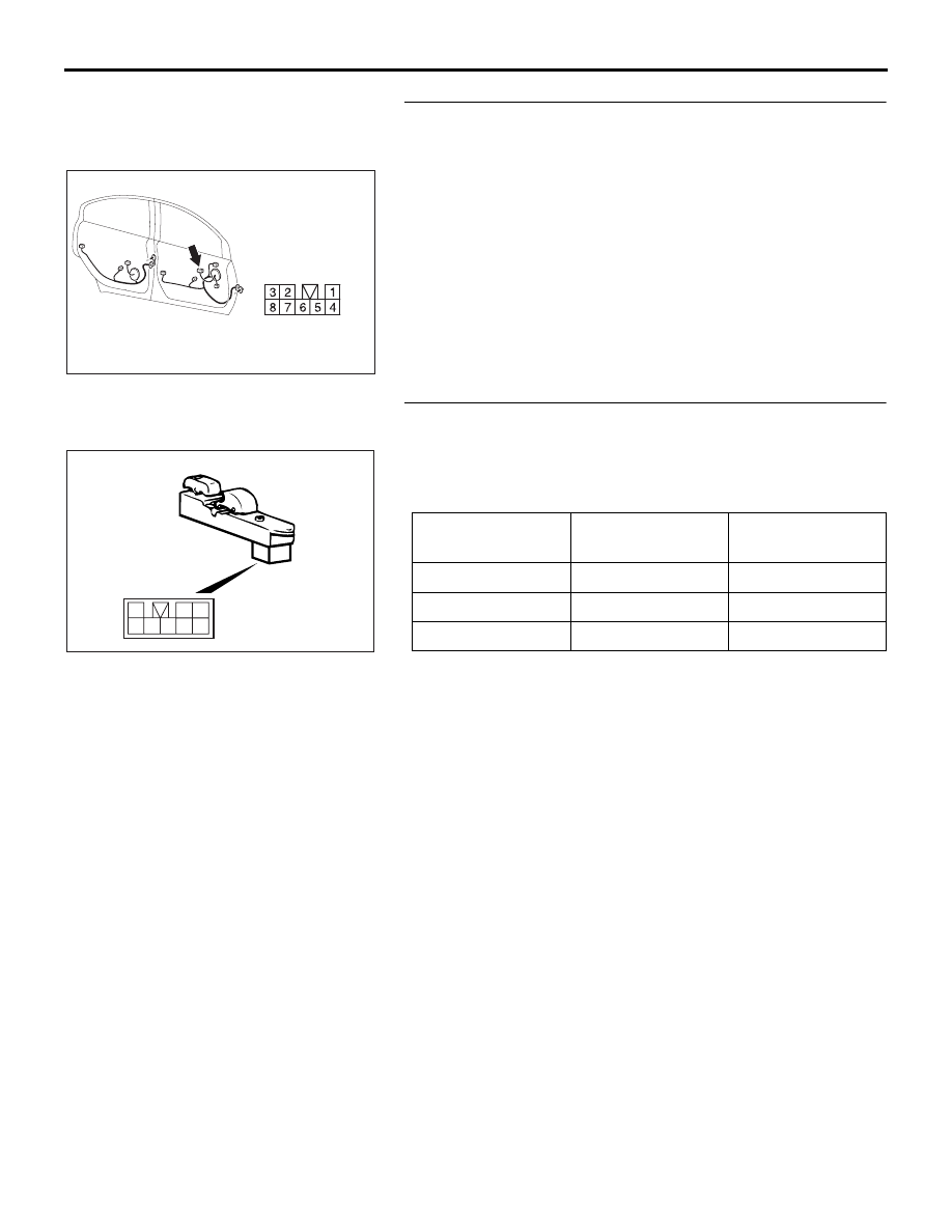
STEP 8. Check power window sub switch connector E-12 
for loose, corroded or damaged terminals, or terminals 
pushed back in the connector.
Q: Is power window sub switch connector E-12 in good 

condition?
YES : 
Go to Step 9.
NO :  Repair or replace the damaged component(s). Refer 

to GROUP 00E, Harness Connector Inspection 

P.00E-2

. If the central door locking system works 

normally, input signal from the door lock switch (front 
power window sub switch) should be normal.

STEP 9. Check the door lock switch (front power window 
sub switch).
Remove the front power window sub switch. Refer to GROUP 
42, Door, Door Glass and Regulator 

P.42-39

Then check con-

tinuity between the switch terminals.

Q: Is the door lock switch (front power window sub switch) 

in good condition?
YES : 
Go to Step 10.
NO :  Replace the front power window sub switch. If the 

central door locking system works normally, input 
signal from the door lock switch (front power window 
sub switch) should be normal.

16DB466A

HARNESS SIDE

CONNECTOR: E-12

SWITCH 
POSITION

TESTER 
CONNECTION

SPECIFIED 
CONDITION

LOCK

− 3

Less than 2 ohms

OFF

− 3, 2 − 3

Open circuit

UNLOCK

− 3

Less than 2 ohms

1

2 3

4 5 6 7 8

AC101220

INPUT SIGNAL PROCEDURES

SIMPLIFIED WIRING SYSTEM (SWS)

54B-466

STEP 10. Check the ground circuit to the front power 
window sub switch. Measure the resistance at front power 
window sub switch connector E-12.
(1) Disconnect front power window sub switch connector E-12 

and measure the resistance available at the wiring harness 
side of the connector.

(2) Measure the resistance value between terminal 3 and 

ground.

• The resistance should be 2 ohms or less.

Q: Is the measured resistance 2 ohms or less?

YES : Go to Step 12.
NO :  Go to Step 11.

STEP 11. Check the wiring harness between front power 
window sub switch E-12 (terminal 3) and ground.

16DB466A

HARNESS SIDE

CONNECTOR: E-12

8

3

7

2

5

6

4

1

16DB468A

CONNECTOR  E-12

(HARNESS SIDE)

16DB466A

HARNESS SIDE

CONNECTOR: E-12

INPUT SIGNAL PROCEDURES

SIMPLIFIED WIRING SYSTEM (SWS)

54B-467

NOTE: Also check intermediate connector C-26 for loose, cor-
roded, or damaged terminals, or terminals pushed back in the 
connector. If intermediate connector C-26 is damaged, repair or 
replace the connector as described in GROUP 00E, Harness 
Connector Inspection 

P.00E-2

.

Q: Is the wiring harness between front power window sub 

switch connector E-12 (terminal 3) and ground in good 
condition?
YES : 
No action is necessary and testing is complete.
NO :  The wiring harness may be damaged or the 

connector(s) may have loose, corroded or damaged 
terminals, or terminals pushed back in the connector. 
Repair the wiring harness as necessary. If the central 
door locking system works normally, input signal from 
the door lock switch should be normal.

STEP 12. Check ETACS-ECU connector C-217 for loose, 
corroded or damaged terminals, or terminals pushed back 
in the connector.
Q: Is ETACS-ECU connector C-217 in good condition?

YES : Go to Step 13.
NO :  Repair or replace the damaged component(s). Refer 

to GROUP 00E, Harness Connector Inspection 

P.00E-2

. If the central door locking system works 

normally, input signal from the door lock switch (front 
power window sub switch) should be normal.

16DB322A

CONNECTOR:C-26

16DB307A

CONNECTOR: C-217

HARNESS SIDE

25

26

27

28

29

21

22

23

24

30

31

32

33

34

35

36

37

38

39

40

41

42

43

44

JUNCTION BLOCK

(REAR VIEW)

INPUT SIGNAL PROCEDURES

SIMPLIFIED WIRING SYSTEM (SWS)

54B-468

STEP 13. Check the wiring harness between front power 
window sub switch connector E-12 (terminals 1 and 2) and 
ETACS-ECU connector C-217 (terminals 33 and 34).

NOTE: Also check intermediate connector C-26 for loose, cor-
roded, or damaged terminals, or terminals pushed back in the 
connector. If intermediate connector C-26 is damaged, repair or 
replace the connector as described in GROUP 00E, Harness 
Connector Inspection 

P.00E-2

.

Q: Is the wiring harness between front power window sub 

switch connector E-12 (terminal 1 and 2) and 
ETACS-ECU connector C-217 (terminals 33 and 34) in 
good condition?
YES : 
Replace the ETACS-ECU. If the central door locking 

system works normally, input signal from the door lock 
switch (front power window sub switch) should be 
normal.

NO :  The wiring harness may be damaged or the 

connector(s) may have loose, corroded or damaged 
terminals, or terminals pushed back in the connector. 
Repair the wiring harness as necessary. If the central 
door locking system works normally, input signal from 
the door lock switch (front power window sub switch) 
should be normal.

16DB307A

CONNECTOR: C-217

HARNESS SIDE

25

26

27

28

29

21

22

23

24

30

31

32

33

34

35

36

37

38

39

40

41

42

43

44

JUNCTION BLOCK

(REAR VIEW)

16DB466A

HARNESS SIDE

CONNECTOR: E-12

16DB322A

CONNECTOR:C-26


Content   ..  115  116  117  118   ..