Mitsubishi 380. Manual - part 115


  Index      Mitsubishi     Mitsubishi 380 - service repair manual 2005 year


Search            


Content   ..  113  114  115  116   ..


Mitsubishi 380. Manual - part 115


INPUT SIGNAL PROCEDURES

SIMPLIFIED WIRING SYSTEM (SWS)

54B-457

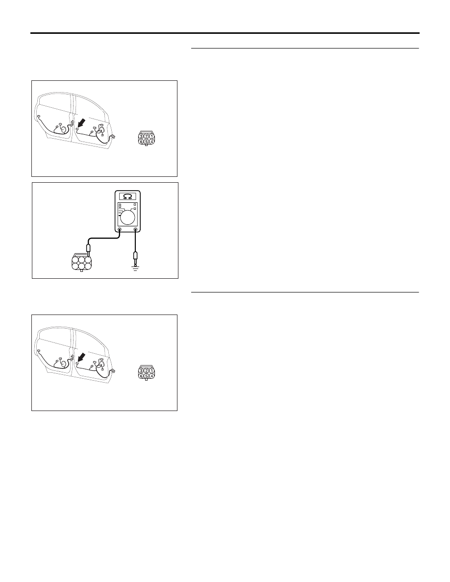
STEP 10. Check the ground circuit to the front door lock 
actuator (LH). Measure the resistance at front door lock 
actuator (LH) connector E-15.
(1) Disconnect front door lock actuator (LH) connector E-15 

and measure the resistance available at the wiring harness 
side of the connector.

(2) Measure the resistance value between terminal 1 and 

ground.

• The resistance should be 2 ohms or less.

Q: Is the measured resistance 2 ohms or less?

YES : Go to Step 12.
NO :  Go to Step 11.

STEP 11. Check the wiring harness between front door 
lock actuator (LH) connector E-15 (terminal 1) and ground.

16DB320A

CONNECTOR: E-15

E-15 (B)

HARNESS SIDE

5

6

4

2

3

1

AC209829

CONNECTOR E-15
(HARNESS SIDE)

AD

16DB320A

CONNECTOR: E-15

E-15 (B)

HARNESS SIDE

INPUT SIGNAL PROCEDURES

SIMPLIFIED WIRING SYSTEM (SWS)

54B-458

NOTE: Also check intermediate connector C-26 for loose, cor-
roded, or damaged terminals, or terminals pushed back in the 
connector. If intermediate connector C-26 is damaged, repair or 
replace the connector as described in GROUP 00E, Harness 
Connector Inspection 

P.00E-2

.

Q: Is the wiring harness between front door lock actuator 

(LH) connector E-15 (terminal 1) and ground in good 
condition?
YES : 
No action is necessary and testing is complete.
NO :  The wiring harness may be damaged or the 

connector(s) may have loose, corroded or damaged 
terminals, or terminals pushed back in the connector. 
Repair the wiring harness as necessary. If the 
functions described in "CIRCUIT OPERATION" work 
normally, the input signal from the front door lock 
actuator (LH) should be normal.

STEP 12. Check ETACS-ECU connector C-217 for loose, 
corroded or damaged terminals, or terminals pushed back 
in the connector.
Q: Is ETACS-ECU connector C-217 in good condition?

YES : Go to Step 13.
NO :  Repair or replace the damaged component(s). Refer 

to GROUP 00E, Harness Connector Inspection 

P.00E-2

. If the functions described in "CIRCUIT 

OPERATION" work normally, the input signal from the 
front door lock actuator (LH) should be normal.

16DB322A

CONNECTOR:C-26

16DB307A

CONNECTOR: C-217

HARNESS SIDE

25

26

27

28

29

21

22

23

24

30

31

32

33

34

35

36

37

38

39

40

41

42

43

44

JUNCTION BLOCK

(REAR VIEW)

INPUT SIGNAL PROCEDURES

SIMPLIFIED WIRING SYSTEM (SWS)

54B-459

STEP 13. Check the wiring harness between front door 
lock actuator (LH) connector E-15 (terminal 3) and 
ETACS-ECU connector C-217 (terminal 43).

NOTE: Also check intermediate connector C-26 for loose, cor-
roded, or damaged terminals, or terminals pushed back in the 
connector. If intermediate connector C-26 is damaged, repair or 
replace the connector as described in GROUP 00E, Harness 
Connector Inspection 

P.00E-2

.

Q: Is the wiring harness between front door lock actuator 

(LH) connector E-15 (terminal 3) and ETACS-ECU 
connector C-217 (terminal 43) in good condition?
YES : 
Replace the ETACS-ECU. If the functions described 

in "CIRCUIT OPERATION" work normally, the input 
signal from the front door lock actuator (LH) should be 
normal.

NO :  The wiring harness may be damaged or the 

connector(s) may have loose, corroded or damaged 
terminals, or terminals pushed back in the connector. 
Repair the wiring harness as necessary. If the 
functions described in "CIRCUIT OPERATION" work 
normally, the input signal from the front door lock 
actuator (LH) should be normal.

16DB307A

CONNECTOR: C-217

HARNESS SIDE

25

26

27

28

29

21

22

23

24

30

31

32

33

34

35

36

37

38

39

40

41

42

43

44

JUNCTION BLOCK

(REAR VIEW)

16DB320A

CONNECTOR: E-15

E-15 (B)

HARNESS SIDE

16DB322A

CONNECTOR:C-26

INPUT SIGNAL PROCEDURES

SIMPLIFIED WIRING SYSTEM (SWS)

54B-460

INSPECTION PROCEDURE N-6: ETACS-ECU does not receive any signal from the door lock switch 
(incorporated in the power window main switch and front power window sub switch).

.

CIRCUIT OPERATION

The ETACS-ECU operates the central door locking 
system according to signal from the door lock switch 
(incorporated in the power window main switch and 
front power window sub switch).

.

TECHNICAL DESCRIPTION (COMMENT)

If the signal is not normal, the doors will not lock or 
unlock. If the signal is not normal, the power window 
main switch, front power window sub switch or the 
ETACS-ECU may be defective.

.

TROUBLESHOOTING HINTS

• Refer to circuit diagrams GROUP-

90

• Refer to configuration diagrams GROUP-

80

• The power window main switch or front power 

window sub switch may be defective

• The wiring harness or connectors may have 

loose, corroded, or damaged terminals, or termi-
nals pushed back in the connector

• The ETACS-ECU may be defective

16DB310A

CONNECTOR: C-12

16DB322A

CONNECTOR:C-26

16DB307A

CONNECTOR: C-217

HARNESS SIDE

25

26

27

28

29

21

22

23

24

30

31

32

33

34

35

36

37

38

39

40

41

42

43

44

JUNCTION BLOCK

(REAR VIEW)

16DB466A

HARNESS SIDE

CONNECTOR: E-12

16DB332A

3

9

4

12

14

6

13

5

1110

8

2

7

1

HARNESS SIDE

CONNECTOR:E-04


Content   ..  113  114  115  116   ..