Mitsubishi 380. Manual - part 73


  Index      Mitsubishi     Mitsubishi 380 - service repair manual 2005 year


Search            


Content   ..  71  72  73  74   ..


Mitsubishi 380. Manual - part 73


SYMPTOM PROCEDURES

SIMPLIFIED WIRING SYSTEM (SWS)

54B-289

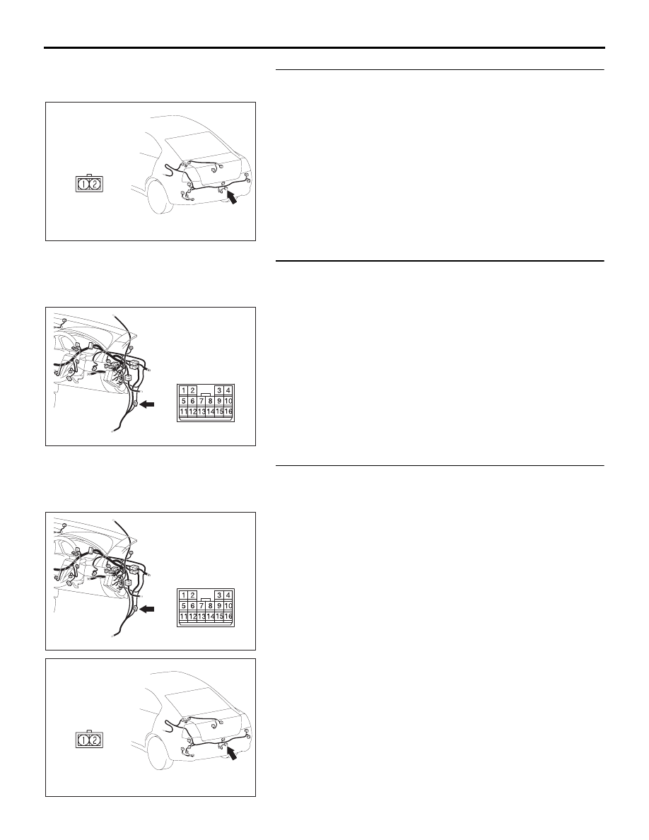
STEP 31. Check the wiring harness between licence plate 
lamp connector F-06 (terminal 1) and ground.
Q: Is the wiring harness between licence plate lamp 

connector F-06 (terminal 1) and ground in good 
condition?
YES : 
Replace the licence plate lamp socket. Verify that the 

licence plate lamps illuminate normally.

NO :  The wiring harness may be damaged or the 

connector(s) may have loose, corroded or damaged 
terminals, or terminals pushed back in the connector. 
Repair the wiring harness as necessary. Verify that 
the licence plate lamps illuminate normally.

STEP 32. Check intermediate connector C-25 for loose, 
corroded or damaged terminals, or terminals pushed back 
in the connector.
Q: Is intermediate connector C-25 in good condition?

YES : Go to Step 33.
NO :  Repair or replace the damaged component(s). Refer 

to GROUP 00E, Harness Connector Inspection 

P.00E-2

. Check that the licence plate lamps illuminate 

normally.

STEP 33. Check the wiring harness between licence plate 
lamp connector F-06 (terminal 2) and intermediate 
connector C-25 (terminal 10).
Q: Is the wiring harness between licence plate lamp 

connector F-06 (terminal 2) and intermediate connector 
C-25 (terminal 10) in good condition?
YES : 
Replace the licence plate lamp socket. Verify that the 

licence plate lamps illuminate normally.

NO :  The wiring harness may be damaged or the 

connector(s) may have loose, corroded or damaged 
terminals, or terminals pushed back in the connector. 
Repair the wiring harness as necessary. Verify that 
the licence plate lamps illuminate normally.

16DB438A

HARNESS SIDE

CONNECTOR: F-06

16DB435A

CONNECTOR: C-25

16DB435A

CONNECTOR: C-25

16DB438A

HARNESS SIDE

CONNECTOR: F-06

SYMPTOM PROCEDURES

SIMPLIFIED WIRING SYSTEM (SWS)

54B-290

INSPECTION PROCEDURE H-7: Headlamp and Taillamp: One of the headlamps does not illuminate. 

.

TECHNICAL DESCRIPTION (COMMENT)

If one of the headlamps does not illuminate, a 
headlamp bulb may be defective.

.

TROUBLESHOOTING HINTS

• Refer to circuit diagrams GROUP-

90

• Refer to configuration diagrams GROUP-

80

• The headlamp bulb may be defective

• The wiring harness or connectors may have 

loose, corroded, or damaged terminals, or termi-
nals pushed back in the connector

.

AC305977AE

CONNECTOR: A-11X

16DB434A

A-20

CONNECTOR: A-20

16DB433A

A-32

CONNECTORS:   A-32

SYMPTOM PROCEDURES

SIMPLIFIED WIRING SYSTEM (SWS)

54B-291

DIAGNOSIS

Required Special Tool:

• MB991223: Harness Set

STEP 1. Check the headlamp operation.

Q: Which of the headlamps does not illuminate?

LH (low beam) : Go to Step 2.
RH (low beam) : Go to Step 6.
LH (only low-beam) : Go to Step 10.
RH (only low-beam) : Go to Step 13.
LH (only high beam) : Go to Step 16.
RH (only high beam) : Go to Step 21.
Low beam only (both RH and LH) : Refer to Inspection 

Procedure H-2 "The headlamps (low-beam) do not 
illuminate normally 

P.54B-264

."

High beam only (both RH and LH) : Refer to Inspection 

Procedure H-3 "The headlamps (high-beam) do not 
illuminate normally 

P.54B-268

."

High beam indicator lamp : Refer to Inspection Procedure 

H-8 "The high-beam indicator lamp does not 
illuminate 

P.54B-301

."

STEP 2. Check headlamp (LH) connector A-20 for loose, 
corroded or damaged terminals, or terminals pushed back 
in the connector.
Q: Is headlamp (LH) connector A-20 in good condition?

YES : Go to Step 3.
NO :  Repair or replace the damaged component(s). Refer 

to GROUP 00E, Harness Connector Inspection 

P.00E-2

. Check that the headlamps illuminate 

normally.

STEP 3. Check headlamp (LH) bulb.
(1) Remove the headlamp (LH) bulb.
(2) Verify that the headlamp (LH) bulb is not damaged or 

burned out.

Q: Is headlamp (LH) bulb normal?

YES : Go to Step 4.
NO :  Replace the headlamp (LH) bulb. Verify that the 

headlamps illuminate normally.

16DB434A

A-20

CONNECTOR: A-20

SYMPTOM PROCEDURES

SIMPLIFIED WIRING SYSTEM (SWS)

54B-292

STEP 4. Check the ground circuit to the front Headlamp 
(LH). Measure the resistance at front combination lamp 
(LH) connector A-20.
(1) Disconnect front combination lamp (LH) connector A-20 

and measure the resistance available at the wiring harness 
side of the connector.

(2) Measure the resistance value between terminal (5) and 

ground.

• The resistance should be 2 ohms or less.

Q: Is the measured resistance 2 ohms or less?

YES : Go to Step 10.
NO :  Go to Step 5.

STEP 5. Check the wiring harness between headlamp (LH) 
connector A-20 (terminal 5) and ground.
Q: Is the wiring harness between headlamp (LH) connector 

A-20 (terminal 5) and ground in good condition?
YES : 
No action is necessary and testing is complete.
NO :  The wiring harness may be damaged or the 

connector(s) may have loose, corroded or damaged 
terminals, or terminals pushed back in the connector. 
Repair the wiring harness as necessary. Verify that 
the headlamps illuminate normally.

STEP 6. Check headlamp (RH) connector A-32 for loose, 
corroded or damaged terminals, or terminals pushed back 
in the connector.
Q: Is headlamp (RH) connector A-32 in good condition?

YES : Go to Step 6.
NO :  Repair or replace the damaged component(s). Refer 

to GROUP 00E, Harness Connector Inspection 

P.00E-2

. Check that the headlamps illuminate 

normally.

16DB434A

A-20

CONNECTOR: A-20

16DB436A

CONNECTOR A-20

(HARNESS SIDE)

16DB434A

A-20

CONNECTOR: A-20

16DB433A

A-32

CONNECTORS:   A-32


Content   ..  71  72  73  74   ..