Mitsubishi 380. Manual - part 66
SYMPTOM PROCEDURES
SIMPLIFIED WIRING SYSTEM (SWS)
54B-261
STEP 1. Use Diagnostic Tool MB991958 to select "ECU
COMM Check" on the SWS monitor display.
Check the following ECUs:
• Column switch (column-ECU)
• Front-ECU
CAUTION
To prevent damage to Diagnostic Tool MB991958, always
turn the ignition switch to the "LOCK" (OFF) position
before connecting or disconnecting Diagnostic Tool
MB991958. Connect special tool MB991910 before con-
necting special tool MB991812. Be sure to connect special
tool MB991806 after turning on special tool MB991824.
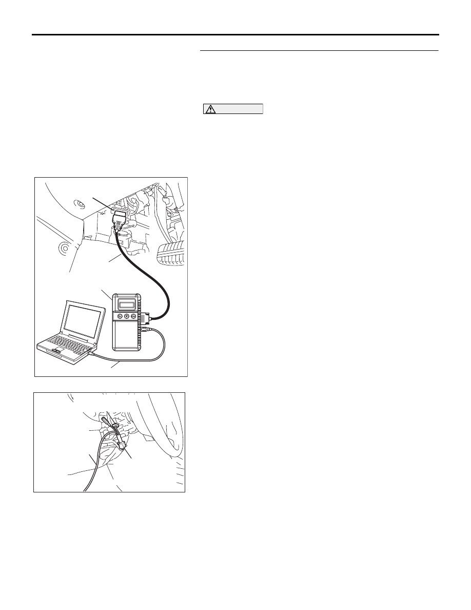
(1) Connect the special tool. Refer to "How to connect SWS
monitor
."
(2) Turn the ignition switch to the "LOCK" (OFF) position.
(3) Operate Diagnostic Tool MB991958 according to the
procedure below to display "ECU COMM Check."
a. Select "Interactive Diagnosis."
b. Select "System select."
c. Select "SWS."
d. Select "SWS MONITOR."
e. Select "ECU COMM Check."
(4) Diagnostic Tool MB991958 should show "OK" on the "ECU
COMM Check" menus for both the "COLUMN ECU" and
the "FRONT ECU" menus.
Q: Is "OK" displayed for both the "COLUMN ECU" and
"FRONT ECU" menu?
"OK" is displayed for all the items : Go to Step 2.
"NG" is displayed for the "COLUMN ECU" menu : Refer
to Inspection Procedure A-2 "Communication with the
column switch (column-ECU) is not possible
."
"NG" is displayed for the "FRONT ECU" menu : Refer to
Inspection Procedure A-4 "Communication with the
front-ECU is not possible
."
00DB076A
MB991910
DATA LINK
CONNECTOR
MB991824
MB991827
AC302210
COLUMN SWITCH
CONNECTOR
COLUMN SWITCH
CONNECTOR AT
HARNESS SIDE
MB991812
AB