Mitsubishi 380. Manual - part 55


  Index      Mitsubishi     Mitsubishi 380 - service repair manual 2005 year


Search            


Content   ..  53  54  55  56   ..


Mitsubishi 380. Manual - part 55


SYMPTOM PROCEDURES

SIMPLIFIED WIRING SYSTEM (SWS)

54B-217

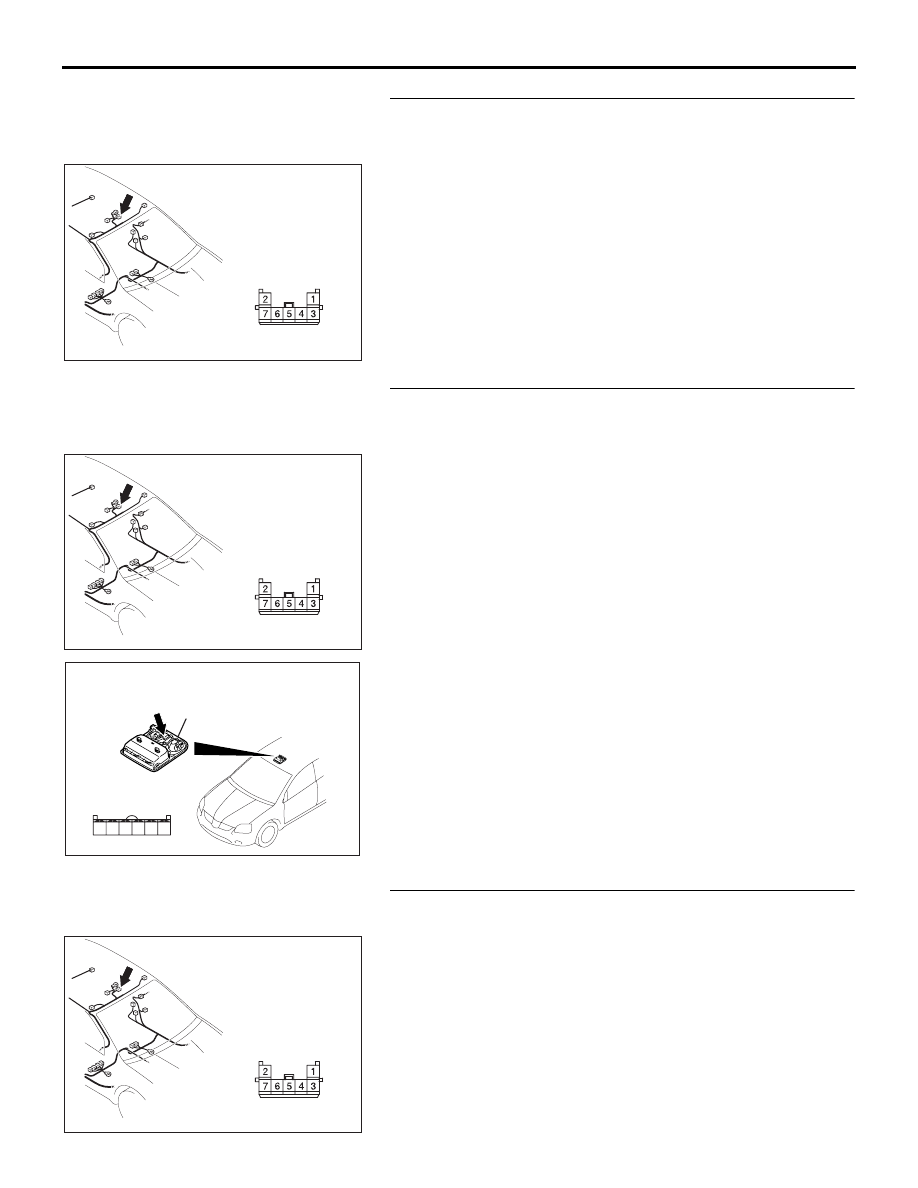
STEP 11. Check overhead console assembly connector 
D-03 for loose, corroded or damaged terminals, or 
terminals pushed back in the connector.
Q: Is overhead console assembly connector D-03 in good 

condition?
YES : 
Go to Step 12.
NO :  Repair or replace the damaged component(s). Refer 

to GROUP 00E, Harness Connector Inspection 

P.00E-2

. Check that the sunroof works normally.

STEP 12. Check the wiring harness between sunroof 
switch connector D-03-1 (terminal 4) and overhead 
console assembly connector D-03 (terminal 6).
Q: Is the wiring harness between sunroof switch connector 

D-03-1 (terminal 4) and overhead console assembly 
connector D-03 (terminal 6) in good condition?
YES : 
Go to Step 13.
NO :  The wiring harness may be damaged or the 

connector(s) may have loose, corroded or damaged 
terminals, or terminals pushed back in the connector. 
Repair the wiring harness as necessary. Check that 
the sunroof works normally.

STEP 13. Check the wiring harness between overhead 
console assembly connector D-03 (terminal 6) and ground.
Q: Is the wiring harness between overhead console 

assembly connector D-03 (terminal 6) and ground in 
good condition?
YES : 
No action is necessary and testing is complete.
NO :  The wiring harness may be damaged or the 

connector(s) may have loose, corroded or damaged 
terminals, or terminals pushed back in the connector. 
Repair the wiring harness as necessary. Check that 
the sunroof works normally.

16DB362A

CONNECTOR: D-03

HARNESS SIDE

16DB362A

CONNECTOR: D-03

HARNESS SIDE

AC307976

OVERHEAD CONSOLE
ASSEMBLY

CONNECTOR: D-03-1

HARNESS SIDE

AB

6

4

5

3 2 1

16DB362A

CONNECTOR: D-03

HARNESS SIDE

SYMPTOM PROCEDURES

SIMPLIFIED WIRING SYSTEM (SWS)

54B-218

STEP 14. Check the wiring harness between sunroof 
switch connector D-03-1 (terminals 3, 5 and 6) and 
overhead console assembly connector D-03 (terminals 7, 5 
and 4).
Q: Is the wiring harness between sunroof switch connector 

D-03-1 (terminals 3, 5 and 6) and overhead console 
assembly connector D-03 (terminals 7, 5 and 4) in good 
condition?
YES : 
Go to Step 15.
NO :  The wiring harness may be damaged or the 

connector(s) may have loose, corroded or damaged 
terminals, or terminals pushed back in the connector. 
Repair the wiring harness as necessary. Check that 
the sunroof works normally.

STEP 15. Check the wiring harness between sunroof motor 
assembly connector D-04 (terminals 6, 7 and 8) and 
overhead console assembly connector D-03 (terminals 4, 7 
and 5).
Q: Is the wiring harness between sunroof motor assembly 

connector D-04 (terminals 6, 7 and 8) and overhead 
console assembly connector D-03 (terminals 4, 7 and 5) 
in good condition?
YES : 
Go to Step 16.
NO :  The wiring harness may be damaged or the 

connector(s) may have loose, corroded or damaged 
terminals, or terminals pushed back in the connector. 
Repair the wiring harness as necessary. Check that 
the sunroof works normally.

STEP 16. Replace the sunroof switch.
(1) Replace the sunroof switch.
(2) Check that the sunroof works normally.

Q: Does the sunroof works normally?

YES : No action is necessary and testing is complete.
NO :  Replace the sunroof motor assembly. Check that the 

sunroof works normally.

16DB362A

CONNECTOR: D-03

HARNESS SIDE

AC307976

OVERHEAD CONSOLE
ASSEMBLY

CONNECTOR: D-03-1

HARNESS SIDE

AB

6

4

5

3 2 1

16DB363A

CONNECTORS: D-03, D-04

D-04

D-03

D-03

D-04

HARNESS SIDE

SYMPTOM PROCEDURES

SIMPLIFIED WIRING SYSTEM (SWS)

54B-219

INSPECTION PROCEDURE F-2: Sunroof: Any of the sunroof switch positions is defective.

.

TECHNICAL DESCRIPTION (COMMENT)

The sunroof switch or the sunroof motor assembly 
may be defective.

.

TROUBLESHOOTING HINTS

• Refer to circuit diagrams GROUP-

90

• Refer to configuration diagrams GROUP-

80

• The sunroof switch may be defective

• The sunroof motor assembly may be defective

• The wiring harness or connectors may have 

loose, corroded, or damaged terminals, or termi-
nals pushed back in the connector

DIAGNOSIS

Required Special Tools:

• MB991223: Harness Set

• MB991958: diagnostic tool (MUT-III Sub Assembly)

• MB991824: Vehicle Communication Interface (V.C.I.)

• MB991827: MUT-III USB Cable

• MB991910: MUT-III Main Harness A

Check the input signal (by using the pulse check mode of 
the monitor).
Check the input signals from the sunroof switch.

CAUTION

To prevent damage to diagnostic tool MB991958, always 
turn the ignition switch to the "LOCK" (OFF) position 
before connecting or disconnecting diagnostic tool 
MB991958.
(1) Connect diagnostic tool MB991958.Refer to "How to 

connect SWS monitor 

P.54B-13

."

(2) Operate the diagnostic tool MB991958 according to the 

procedure below to display "Pulse check."
a. Select "Interactive Diagnosis."
b. Select "System select."
c. Select "SWS."
d. Select "Pulse Checking."

(3) When each function of the sunroof switch is operated 

(turned on), check that diagnostic tool MB991958 sounds.

Q: Does diagnostic tool MB991958 sound when the 

sunroof switch is operated?
YES : 
Replace the sunroof motor assembly. Check that the 

sunroof works at all positions normally.

NO :  Refer to Inspection Procedure M-8 "ETACS-ECU 

does not receive any signal from the up, open or 
close/down switch 

P.54B-429

."

00DB076A

MB991910

DATA LINK

CONNECTOR

MB991824

MB991827

SYMPTOM PROCEDURES

SIMPLIFIED WIRING SYSTEM (SWS)

54B-220

INSPECTION PROCEDURE F-3: Sunroof: Sunroof Timer Function does not Work Normally.

NOTE: This troubleshooting requires use of 
diagnostic tool MB991958 and SWS monitor kit 
MB991813. For details of how to use the SWS moni-
tor, refer to "How to connect SWS monitor 

P.54B-13

."

.

CIRCUIT OPERATION

• The sunroof timer function works according to the 

signals from the following switches:

• Ignition switch (IG1): OFF

• Front door switch: OFF

• Vehicle condition

• Ignition switch: LOCK position

• Front door: Closed

• When the driver’s door is opened and closed 

while the sunroof timer function is on, the sunroof 
operative duration will be changed.

.

TECHNICAL DESCRIPTION (COMMENT)

Is the sunroof timer function does not work normally, 
the input circuits from the switches described in 
"CIRCUIT OPERATION", the sunroof motor assem-
bly, the ETACS-ECU or the SWS communication line 
may be defective.

.

TROUBLESHOOTING HINTS

• Refer to circuit diagrams GROUP-

90

• Refer to configuration diagrams GROUP-

80

• The front door switch may be defective

• The sunroof motor assembly may be defective

• The wiring harness or connectors may have 

loose, corroded, or damaged terminals, or termi-
nals pushed back in the connector

DIAGNOSIS

Required Special Tools:

• MB991223: Test Harness Set

• MB991958: diagnostic tool (MUT-III Sub Assembly)

• MB991824: Vehicle Communication Interface (V.C.I.)

• MB991827: MUT-III USB Cable

• MB991910: MUT-III Main Harness A

• MB991813: SWS Monitor Kit

• MB991806: SWS Monitor Cartridge

• MB991812: SWS Monitor Harness (For Column-ECU)

• MB991822: Test Probe Harness

SUNROOF-ECU

SUNROOF MOTOR

ASSEMBLY

· 

FRONT DOOR

 SWITCH (LH)

· IGNITION SWITCH (IG1)

· SUNROOF ECU ACK

INPUT SIGNAL

Sunroof Timer Function


Content   ..  53  54  55  56   ..