Mitsubishi 380. Manual - part 12
DIAGNOSTIC TROUBLE CODE PROCEDURES
SIMPLIFIED WIRING SYSTEM (SWS)
54B-45
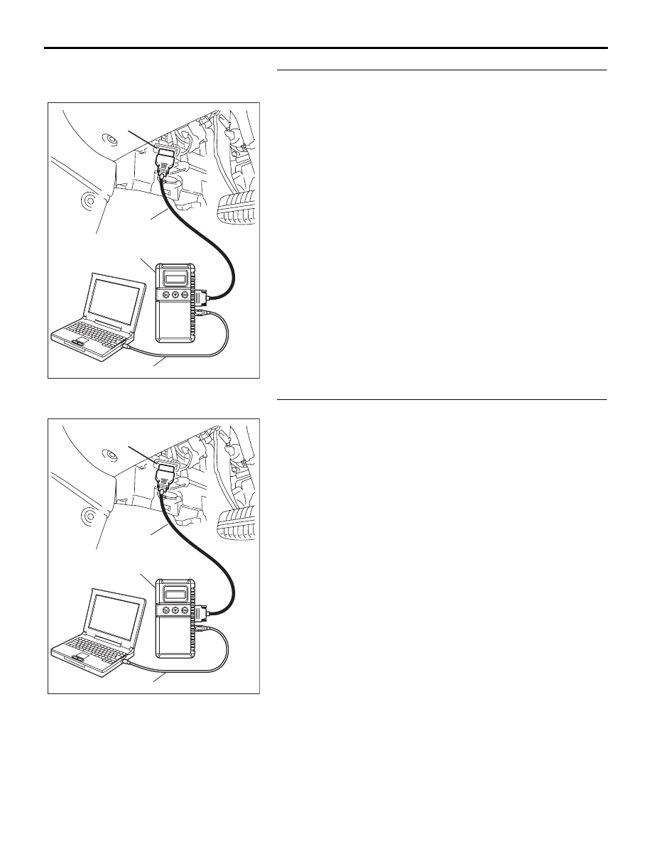
STEP 3. Using diagnostic tool MB991958, read the for any
diagnostic trouble code.
Check if a DTC, which relates to CAN communication-linked
systems below, is set.
• Combination meter
A/C-related time-out DTC
• Multi center display <Vehicles with multi center display >
A/C-related time-out DTC
(1) Turn the ignition switch to the "ON" position.
(2) Check for a DTC related to the relevant system.
(3) Turn the ignition switch to the "LOCK" (OFF) position.
Q: Is the DTC set?
YES : Go to Step 4.
NO : Go to Step 5.
STEP 4. Recheck for diagnostic trouble code.
Check again if the DTC is set.
(1) Turn the ignition switch to the "ON" position.
(2) Check if the DTC is set.
(3) Turn the ignition switch to the "LOCK" (OFF) position.
Q: Is the DTC set?
YES : Replace the A/C-ECU. On completion, verify that the
DTC is not reset.
NO : A poor connection, open circuit or other intermittent
malfunction is present in the CAN bus lines between
the A/C-ECU and the ETACS-ECU (Refer to GROUP
00, How to Cope with Intermittent Malfunction
).
00DB076A
MB991910
DATA LINK
CONNECTOR
MB991824
MB991827
00DB076A
MB991910
DATA LINK
CONNECTOR
MB991824
MB991827