Mitsubishi Grandis. Manual - part 960
HYDRAULIC UNIT
TRACTION CONTROL/ACTIVE STABILITY CONTROL SYSTEM
35C-165
HYDRAULIC UNIT
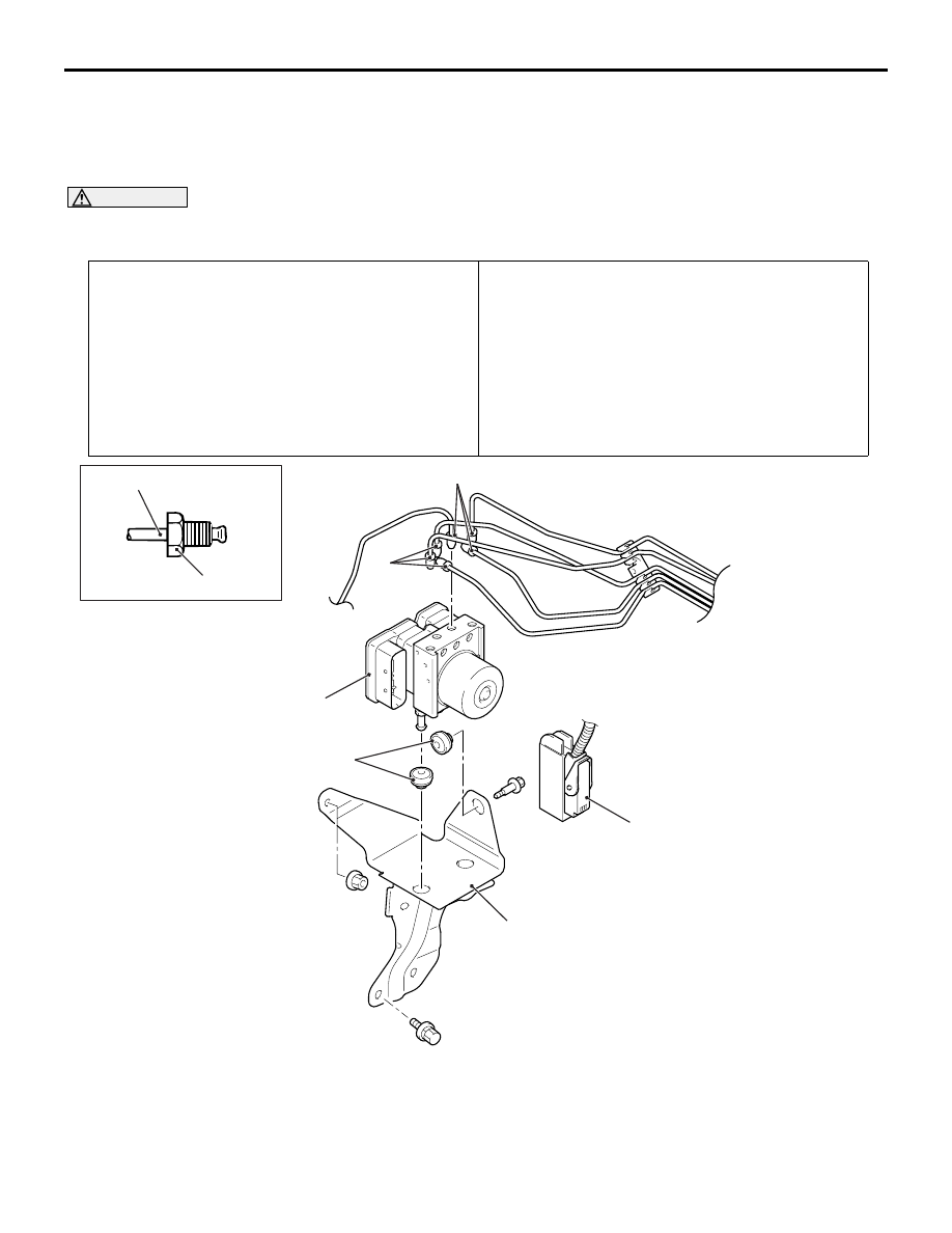
REMOVAL AND INSTALLATION
M1355005600033
NOTE: The TCL/ASC-ECU is integrated in the hydraulic unit.
CAUTION
Always calibrate the steering wheel sensor and the G and yaw rate sensor if the hydraulic unit
(integrated in the TCL/ASC-ECU) is replaced.(Refer to
Pre-removal Operation
• Brake Fluid Draining
• Engine cover removal (Refer to GROUP 11A - Camshaft
and valve stem seal
.)
• Air cleaner body assembly removal (Refer to GROUP 15 -
Air Cleaner
• Canister removal (Refer to GROUP 17 - Canister
.) <LH drive vehicles>
Post-installation Operation
• Canister installation (Refer to GROUP 17 - canister
.) <LH drive vehicles>
• Air cleaner body assembly installation (Refer to GROUP
15 - Air Cleaner
• Engine cover installation (Refer to GROUP 11A -
• Brake Fluid Filling
• Brake Line Bleeding (Refer to GROUP 35A, On-vehicle
Service
− Bleeding
• Hydraulic Unit Check (Refer to
AC312595
15 ± 2 N·m
2
AB
4
1
5
3
2
2