Mitsubishi Grandis. Manual - part 942


  Index      Mitsubishi     Mitsubishi Grandis - service repair manual


Search            


Content   ..  940  941  942  943   ..


Mitsubishi Grandis. Manual - part 942


TROUBLESHOOTING

TRACTION CONTROL/ACTIVE STABILITY CONTROL SYSTEM

35C-93

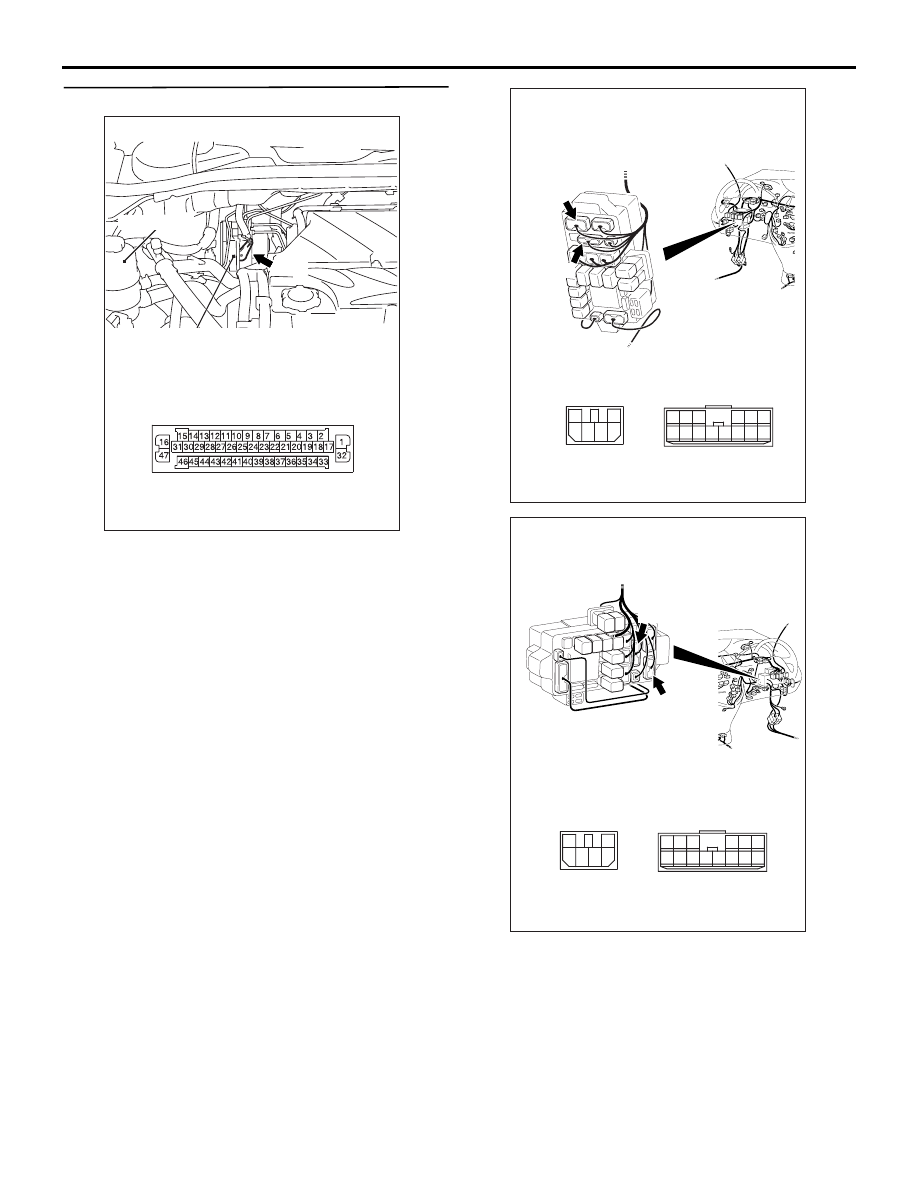
STEP 6. Check the following connectors.

TCL/ASC-ECU connector A-04

Junction block connectors C-202 and C-203

AC312621

Oil reservoir

Connector: A-04

AB

A-04

Hydraulic unit
(with built-in TCL/ASC-ECU)

A-04 Harness connector
(harness side)

AC313139

AB

C-203

Connectors: C-202, C-203
<L.H.drive vehicles>

C-202

C-202

C-203

1

3 4

2

6

5

6

1

7

2

9

8

10

3

5

12

11

4

1314

Junction block
(Front view)

AC313140

AB

C-203

Connectors: C-202, C-203
<R.H.drive vehicles>

C-202

C-202

C-203

1

3 4

2

6

5

6

1

7

2

9

8

10

3

5

12

11

4

1314

Junction block
(Front view)

TROUBLESHOOTING

TRACTION CONTROL/ACTIVE STABILITY CONTROL SYSTEM

35C-94

Joint connector C-01 <LH drive vehicles> or C-33 

<RH drive vehicles> and intermediate connector 
C-124

Ignition switch connector C-307
Check the connectors, for loose, corroded or 
damaged terminals, or terminals pushed back in the 
connector.

Q: Is the check result normal?

YES : 

An open or short circuit may be present in 

the power supply line to the TCL/ASC-ECU. 
Repair the wiring harness between 
TCL/ASC-ECU connector A-04 terminal 32 
and ignition switch connector C-307 
terminal 2. Then go to Step 8.

NO : 

Repair or replace the damaged 
component(s). Then go to Step 8.

AC211226

33

22

11

28

17

16

15

14

13

12

25

2324

2627

3

1 2

4 5

21

20

19

18
2930

32

31

7

6

8

10

9

AC

CONNECTOR: C-04

C-04

AC312624

33

22

11

28

17

16

15

14

13

12

25

2324

2627

3

1 2

4 5

21

20

19

18
2930

32

31

7

6

8

10

9

AC

Connectors: C-01, C-124
<L.H.drive vehicles>

C-01

C-01

C-124

C-124

AC312625AC

Connectors: C-33, C-124
<R.H.drive vehicles>

C-33

C-33

C-124

C-124

AC313147AB

Connector: C-307
<L.H.drive vehicles>

C-307

2
5

4

1

6

3

AC313148

AB

Connector: C-307
<R.H.drive vehicles>

C-307

2
5

4

1

6

3

TROUBLESHOOTING

TRACTION CONTROL/ACTIVE STABILITY CONTROL SYSTEM

35C-95

STEP 7. Check whether the diagnosis code is 
reset.

CAUTION

Before connecting or disconnecting the MUT-III, 
turn the ignition switch to the "LOCK" (OFF) 
position.
Check again if the diagnosis code is set.
(1) Turn the ignition switch to the "ON" position.
(2) Erase the diagnosis code.
(3) Turn the ignition switch to the "LOCK" (OFF) 

position.

(4) Turn the ignition switch to the "ON" position.
(5) Check if the diagnosis code is set.
(6) Turn the ignition switch to the "LOCK" (OFF) 

position.

Q: Is code No.C1860 or C1861 set?

YES : 

Replace the hydraulic unit (integrated with 

TCL/ASC-ECU). Then go to Step 8.

NO : 

It can be assumed that this malfunction is 
intermittent. Refer to GROUP 00, How to 
Use Troubleshooting/Inspection Service 
Points 

− How to Cope with Intermittent 

Malfunction 

P.00-5

.

STEP 8. Check whether the diagnosis code is 
reset.

CAUTION

Before connecting or disconnecting the MUT-III, 
turn the ignition switch to the "LOCK" (OFF) 
position.
Check again if the diagnosis code is set.
(1) Turn the ignition switch to the "ON" position.
(2) Erase the diagnosis code.
(3) Turn the ignition switch to the "LOCK" (OFF) 

position.

(4) Turn the ignition switch to the "ON" position.
(5) Check if the diagnosis code is set.
(6) Turn the ignition switch to the "LOCK" (OFF) 

position.

Q: Is code No.C1860 or C1861 set?

YES : 

Go to Step 1.

NO : 

The procedure is complete.

AC302297

AC310120

AB

MB991827

16-pin

MB991910

MB991824

AC302297

AC310120

AB

MB991827

16-pin

MB991910

MB991824

TROUBLESHOOTING

TRACTION CONTROL/ACTIVE STABILITY CONTROL SYSTEM

35C-96

Code No.C1864: Sensor cluster power supply abnormality

CAUTION

If there is any problem in the CAN bus lines, an 
incorrect diagnosis code may be set. Prior to this 
diagnosis, diagnose the CAN bus lines.

OPERATION

• The G and yaw late sensor is energized by the 

TCL/ASC-ECU and the G and yaw late sensor 
terminal 1.

• The G and yaw late sensor output signal is sent 

to the TCL/ASC-ECU via the CAN bus line.

DIAGNOSIS CODE SET CONDITIONS

These codes are set when the power supply to the G 
and yaw late sensor is not normal.

PROBABLE CAUSES

• Malfunction of the G and yaw late sensor

• Damaged wiring harness or connector

• Malfunction of the hydraulic unit (integrated with 

TCL/ASC-ECU)

TCL/ASC-ECU

Wire colour code
B : Black     LG : Light green     G : Green     L : Blue     W : White     Y : Yellow     SB : Sky blue
BR : Brown     O : Orange     GR : Gray     R : Red     P : Pink     V : Violet   

G AND YAW 
LATE SENSOR

G and Yaw Late Sensor Circuit


Content   ..  940  941  942  943   ..