Mitsubishi Grandis. Manual - part 911
TROUBLESHOOTING
ANTI-SKID BRAKING SYSTEM (ABS)
35B-59
STEP 8. Check whether the diagnosis code is
reset.
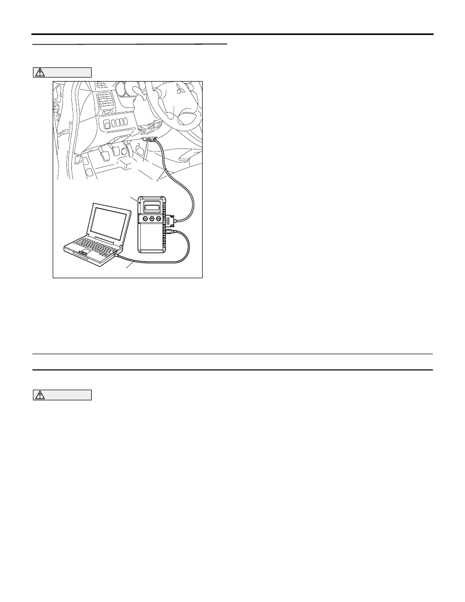
CAUTION
Before connecting or disconnecting the MUT-III,
turn the ignition switch to the "LOCK" (OFF)
position.
Check again if the diagnosis code is set.
(1) Turn the ignition switch to the "ON" position.
(2) Erase the diagnosis code.
(3) Turn the ignition switch to the "LOCK" (OFF)
position.
(4) Turn the ignition switch to the "ON" position.
(5) Check if the diagnosis code is set.
(6) Turn the ignition switch to the "LOCK" (OFF)
position.
Q: Is code No.C1860 or C1861 set?
YES :
Go to Step 1.
NO :
The procedure is complete.
Code No.U1073: Bus off
CAUTION
• If diagnosis code U1073 is set in the
ABS-ECU, always diagnose the CAN main bus
line. If there is any fault in the CAN bus lines,
an incorrect diagnosis code may be set.
• Whenever the ECU is replaced, ensure that
the communication circuit is normal.
TROUBLE JUDGMENT
This code is stored when the ABS-ECU has ceased
the CAN communication (bus off). Then, if a penalty
mode is entered after approximately five minutes,
regular data transmission will be cancelled.
PROBABLE CAUSES
• Damaged wiring harness or connector
• Malfunction of the hydraulic unit (integrated with
ABS-ECU)
AC302297
AC310120
AB
MB991827
16-pin
MB991910
MB991824