Mitsubishi Grandis. Manual - part 910


  Index      Mitsubishi     Mitsubishi Grandis - service repair manual


Search            


Content   ..  908  909  910  911   ..


Mitsubishi Grandis. Manual - part 910


TROUBLESHOOTING

ANTI-SKID BRAKING SYSTEM (ABS)

35B-55

DIAGNOSIS

STEP 1. MUT-III CAN bus diagnostics
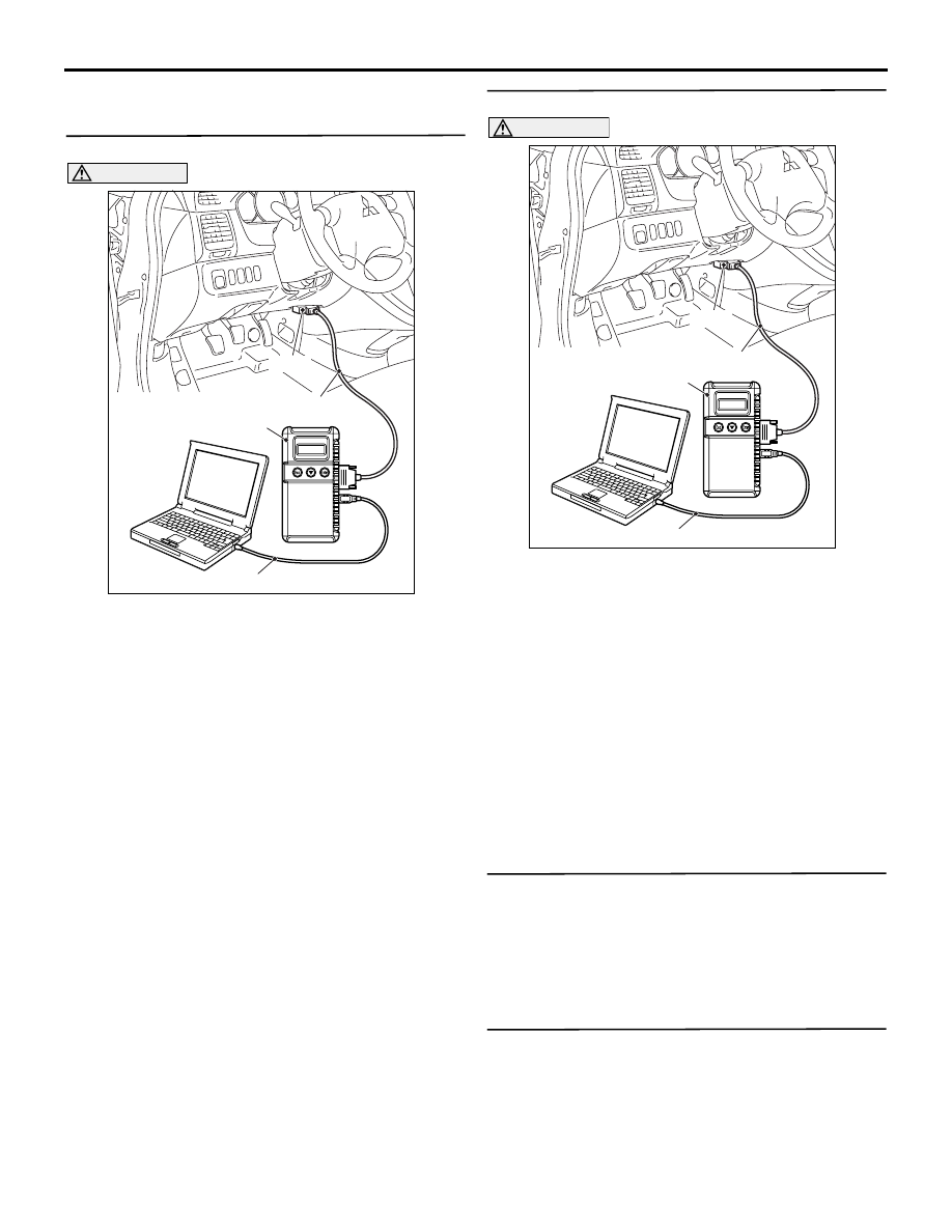
CAUTION

Before connecting or disconnecting the MUT-III, 
turn the ignition switch to the "LOCK" (OFF) 
position.
(1) Connect MUT-III to the 16-pin diagnosis 

connector.

(2) Turn the ignition switch to the "ON" position.
(3) Diagnose the CAN bus line.
(4) Turn the ignition switch to the "LOCK" (OFF) 

position.

Q: Is the check result normal?

YES : 

Go to Step 3.

NO : 

Repair the CAN bus line (Refer to GROUP 
54D, CAN bus line Diagnostic flow 

P.54D-9

). Then go to Step 2.

STEP 2. MUT-III diagnosis code

CAUTION

Before connecting or disconnecting the MUT-III, 
turn the ignition switch to the "LOCK" (OFF) 
position.
(1) Turn the ignition switch to the "ON" position.
(2) Erase the diagnosis code.
(3) Turn the ignition switch to the "LOCK" (OFF) 

position.

(4) Turn the ignition switch to the "ON" position.
(5) Check if the diagnosis code is set.
(6) Turn the ignition switch to the "LOCK" (OFF) 

position.

Q: Is code No.C1860 or C1861 set?

YES : 

Go to Step 3.

NO : 

The procedure is complete.

STEP 3. Check the battery.

Check the battery (Refer to GROUP 54A, Battery 
test 

P.54A-6

).

Q: Is the check result normal?

YES : 

Go to Step 4.

NO : 

Charge or replace the battery.

STEP 4. Check the charging system.

Check the charging system (Refer to GROUP 16, 
Charging system 

P.16-5

).

Q: Is the check result normal?

YES : 

Go to Step 5.

NO : 

Repair or replace the charging system 
component(s).

AC302297

AC310120

AB

MB991827

16-pin

MB991910

MB991824

AC302297

AC310120

AB

MB991827

16-pin

MB991910

MB991824

TROUBLESHOOTING

ANTI-SKID BRAKING SYSTEM (ABS)

35B-56

STEP 5. Voltage measurement at ABS-ECU 
connector A-03.

(1) Disconnect the connector A-03, and connect 

special tool ABS Check Harness (MB991974) to 
the wiring harness-side connector.
NOTE: Do not connect special tool ABS Check 
Harness (MB991974) to the ABS-ECU.

(2) Turn the ignition switch to the "ON" position.
(3) Measure the voltage between terminal 20 and 

earth.

OK: System voltage

Q: Is the check result normal?

YES : 

Go to Step 7.

NO : 

Go to Step 6.

AC312620AK

Oil reservoir

Connector: A-03

ABS-ECU

MB991974

Check connector

A-03 Harness connector

A-03

Hydraulic unit
(with built-in ABS-ECU)

TROUBLESHOOTING

ANTI-SKID BRAKING SYSTEM (ABS)

35B-57

STEP 6. Check the following connectors.

ABS-ECU connector A-03

Junction block connectors C-202 and C-203

AC312621

Oil reservoir

Connector: A-03

AC

A-03

Hydraulic unit
(with built-in ABS-ECU)

A-03 Harness connector
(harness side)

AC313139

AB

C-203

Connectors: C-202, C-203
<L.H.drive vehicles>

C-202

C-202

C-203

1

3 4

2

6

5

6

1

7

2

9

8

10

3

5

12

11

4

1314

Junction block
(Front view)

AC313140

AB

C-203

Connectors: C-202, C-203
<R.H.drive vehicles>

C-202

C-202

C-203

1

3 4

2

6

5

6

1

7

2

9

8

10

3

5

12

11

4

1314

Junction block
(Front view)

TROUBLESHOOTING

ANTI-SKID BRAKING SYSTEM (ABS)

35B-58

Joint connector C-01 <LH drive vehicles> or C-33 

<RH drive vehicles> and intermediate connector 
C-124

Ignition switch connector C-307
Check the connectors, for loose, corroded or 
damaged terminals, or terminals pushed back in the 
connector.

Q: Is the check result normal?

YES : 

An open or short circuit may be present in 

the power supply line to the ABS-ECU. 
Repair the wiring harness between 
ABS-ECU connector A-03 terminal 20 and 
ignition switch connector C-307 terminal 2. 
Then go to Step 8.

NO : 

Repair or replace the damaged 
component(s). Then go to Step 8.

STEP 7. Check whether the diagnosis code is 
reset.

CAUTION

Before connecting or disconnecting the MUT-III, 
turn the ignition switch to the "LOCK" (OFF) 
position.
Check again if the diagnosis code is set.
(1) Turn the ignition switch to the "ON" position.
(2) Erase the diagnosis code.
(3) Turn the ignition switch to the "LOCK" (OFF) 

position.

(4) Turn the ignition switch to the "ON" position.
(5) Check if the diagnosis code is set.
(6) Turn the ignition switch to the "LOCK" (OFF) 

position.

Q: Is code No.C1860 or C1861 set?

YES : 

Replace the hydraulic unit (integrated with 

ABS-ECU). Then go to Step 8.

NO : 

It can be assumed that this malfunction is 
intermittent. Refer to GROUP 00, How to 
Use Troubleshooting/Inspection Service 
Points 

− How to Cope with Intermittent 

Malfunction 

P.00-5

.

AC312624

33

22

11

28

17

16

15

14

13

12

25

2324

2627

3

1 2

4 5

21

20

19

18
2930

32

31

7

6

8

10

9

AC

Connectors: C-01, C-124
<L.H.drive vehicles>

C-01

C-01

C-124

C-124

AC312625AC

Connectors: C-33, C-124
<R.H.drive vehicles>

C-33

C-33

C-124

C-124

AC313147AB

Connector: C-307
<L.H.drive vehicles>

C-307

2
5

4

1

6

3

AC313148

AB

Connector: C-307
<R.H.drive vehicles>

C-307

2
5

4

1

6

3

AC302297

AC310120

AB

MB991827

16-pin

MB991910

MB991824


Content   ..  908  909  910  911   ..