Mitsubishi Grandis. Manual - part 896
REAR DISC BRAKE ASSEMBLY
BASIC BRAKE SYSTEM
35A-26
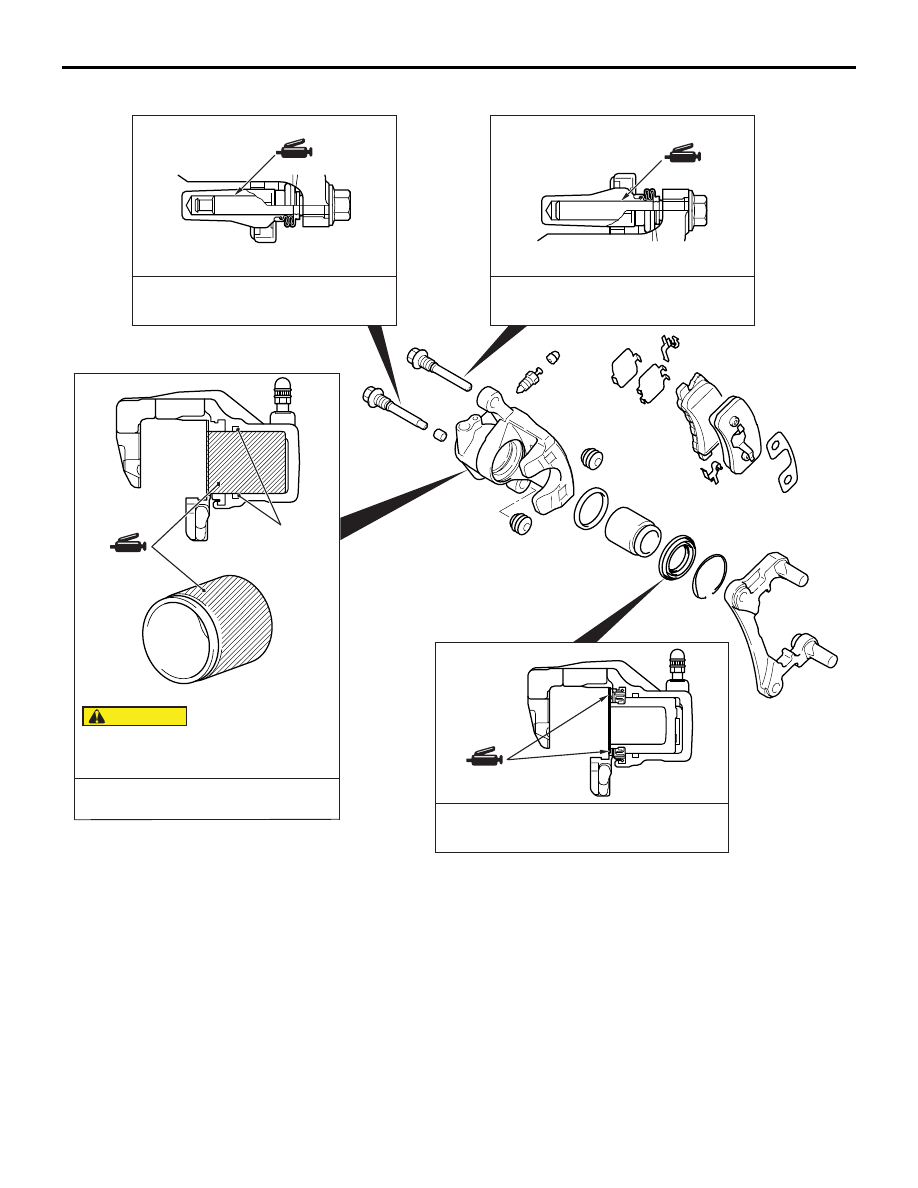
LUBRICATION POINTS
DISASSEMBLY SERVICE POINTS
When disassembling the disc brakes, disassemble
both sides (left and right) as a set.
AC303402
AC
Piston seal
Brake fluid: DOT 3 or DOT 4
Grease: Repair kit grease
The piston seal inside the seal and boot
kit is coated with a special grease.
Do not wipe this grease off.
Grease: Repair kit grease
Grease: Repair kit grease
CAUTION