Mitsubishi Grandis. Manual - part 839


  Index      Mitsubishi     Mitsubishi Grandis - service repair manual


Search            


Content   ..  837  838  839  840   ..


Mitsubishi Grandis. Manual - part 839


TROUBLESHOOTING <A/T>

AUTOMATIC TRANSMISSION (FF)

23A-23

STEP 13. Check the harness between A/T control 
solenoid valve assembly connector B-109 
terminal No.1 and engine-A/T-ECU connector 
C-113 terminal No.119.

Check the output line for short-circuited or open 
circuit.

Q: Is the check result normal?

YES : 

Go to Step 7.

NO : 

Repair the wiring harness.

STEP 14. Check the harness between A/T control 
solenoid valve assembly connector B-109 
terminal No.2 and engine-A/T-ECU connector 
C-113 terminal No.96.

Check the earth line for open circuit.

Q: Is the check result normal?

YES : 

Go to Step 7.

NO : 

Repair the wiring harness.

Code No.16: A/T fluid temperature sensor system (short circuit)

A/T FLUID TEMPERATURE SENSOR 
SYSTEM CIRCUIT

 Refer to 

P.23A-18

.

OPERATION

 Refer to 

P.23A-18

.

DIAGNOSIS CODE SET CONDITION

If the A/T fluid temperature sensor output voltage has 
been approximately 0 V for at least one second 
(indicating abnormally high oil temperature), it 
indicates that the A/T fluid temperature sensor circuit 
is shorted and diagnosis code No.16 will be set.
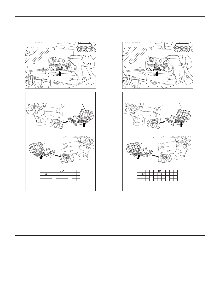
AC303628

B-109 (GR)

Harness side

AG

Connector: B-109

AC311284

Engine-A/T-ECU

Harness side

Engine-A/T-ECU

C-113 (GR)

C-113 (GR)

104

93

95

98

92

94

96

97

99

100

91

103
110

111

101

108

109

105

107

106

102

115

117

112

118

116

114 113

120 119

AF

Connector: C-113 <LHD>

Connector: C-113 <RHD>

TROUBLESHOOTING <A/T>

AUTOMATIC TRANSMISSION (FF)

23A-24

POSSIBLE CAUSES

• Malfunction of the A/T fluid temperature sensor

• Damaged harness wires and connectors

• Malfunction of the engine-A/T-ECU

DIAGNOSIS

STEP 1. MUT-III data list

Item 15: A/T fluid temperature sensor (Refer to Data 
List Tabl

P.23A-117

). 

Q: Is the check result normal?

YES : 

Intermittent malfunction (Refer to GROUP 

00 

− How to Cope with Intermittent 

Malfunction 

P.00-5

).

NO : 

Go to Step 2.

STEP 2. Connector check: B-109 A/T control 
solenoid valve assembly

Check for the contact with terminals.

Q: Is the check result normal?

YES : 

Go to Step 3.

NO : 

Repair the defective connector.

STEP 3. Measure the voltage at A/T control 
solenoid valve assembly connector B-109.

(1) Disconnect the connector, and measure the 

voltage between terminal 1 and earth at the 

wiring harness side.

(2) Turn the ignition switch to the ON position.

OK: 4.5 

 4.9 V

Q: Is the check result normal?

YES : 

Go to Step 4.

NO : 

Go to Step 6.

STEP 4. Measure the resistance at A/T control 
solenoid valve assembly connector B-109.

Disconnect the connector, and measure the 
resistance between terminal 1 and 2 at the sensor 
side.

OK: 

• 16.7  20.5 k (at 0°C)

• 7.3  8.9 k (at 20°C)

• 3.4  4.2 k (at 40°C)

• 1.9  2.2 k (at 60°C)

• 1.0  1.2 k (at 80°C)

• 0.57  0.69 k (at 100°C)

Q: Is the check result normal?

YES : 

Go to Step 5.

NO : 

Replace the A/T fluid temperature sensor.

STEP 5. MUT-III data list

Item 15: A/T fluid temperature sensor (Refer to Data 
List Table 

P.23A-117

). 

Q: Is the check result normal?

YES : 

Intermittent malfunction (Refer to GROUP 

00 

− How to Cope with Intermittent 

Malfunction 

P.00-5

).

NO : 

Replace the engine-A/T-ECU.

STEP 6. Measure the voltage at engine-A/T-ECU 
connector C-113.
(1) Connect A/T control solenoid valve assembly 

connector B-109.

AC303628

B-109 (GR)

Harness side

AG

Connector: B-109

AC303628

B-109 (GR)

Harness side

AG

Connector: B-109

AC303628AF

B-109 (GR)

Connector: B-109

Sensor side

TROUBLESHOOTING <A/T>

AUTOMATIC TRANSMISSION (FF)

23A-25

(2) Turn the ignition switch to the ON position.

(3) Measure the voltage between engine-A/T-ECU 

connector C-113 terminal No.119 and earth. 

OK: 

• 3.8  4.0 V (at 20°C)

• 3.2  3.4 V (at 40°C)

• 1.7  1.9 V (at 80°C)

Q: Is the check result normal?

YES : 

Go to Step 5.

NO : 

Go to Step 7.

STEP 7. Connector check: C-113 engine-A/T-ECU 
connector

Check for the contact with terminals.

Q: Is the check result normal?

YES : 

Go to Step 8.

NO : 

Repair the defective connector.

AC311284

Engine-A/T-ECU

Harness side

Engine-A/T-ECU

C-113 (GR)

C-113 (GR)

104

93

95

98

92

94

96

97

99

100

91

103
110

111

101

108

109

105

107

106

102

115

117

112

118

116

114 113

120 119

AF

Connector: C-113 <LHD>

Connector: C-113 <RHD>

AC311284

Engine-A/T-ECU

Harness side

Engine-A/T-ECU

C-113 (GR)

C-113 (GR)

104

93

95

98

92

94

96

97

99

100

91

103
110

111

101

108

109

105

107

106

102

115

117

112

118

116

114 113

120 119

AF

Connector: C-113 <LHD>

Connector: C-113 <RHD>

TROUBLESHOOTING <A/T>

AUTOMATIC TRANSMISSION (FF)

23A-26

STEP 8. Check the harness between A/T control 
solenoid valve assembly connector B-109 
terminal No.1 and engine-A/T-ECU connector 
C-113 terminal No.119.

Check the output line for short-circuited or open 
circuit.

Q: Is the check result normal?

YES : 

Go to Step 5.

NO : 

Repair the wiring harness.

AC303628

B-109 (GR)

Harness side

AG

Connector: B-109

AC311284

Engine-A/T-ECU

Harness side

Engine-A/T-ECU

C-113 (GR)

C-113 (GR)

104

93

95

98

92

94

96

97

99

100

91

103
110

111

101

108

109

105

107

106

102

115

117

112

118

116

114 113

120 119

AF

Connector: C-113 <LHD>

Connector: C-113 <RHD>


Content   ..  837  838  839  840   ..