Mitsubishi Grandis. Manual - part 838


  Index      Mitsubishi     Mitsubishi Grandis - service repair manual


Search            


Content   ..  836  837  838  839   ..


Mitsubishi Grandis. Manual - part 838


TROUBLESHOOTING <A/T>

AUTOMATIC TRANSMISSION (FF)

23A-19

DIAGNOSIS

STEP 1. MUT-III data list

Item 15: A/T fluid temperature sensor (Refer to Data 
List Tabl

P.23A-117

). 

Q: Is the check result normal?

YES : 

Intermittent malfunction (Refer to GROUP 

00 

− How to Cope with Intermittent 

Malfunction 

P.00-5

).

NO : 

Go to Step 2.

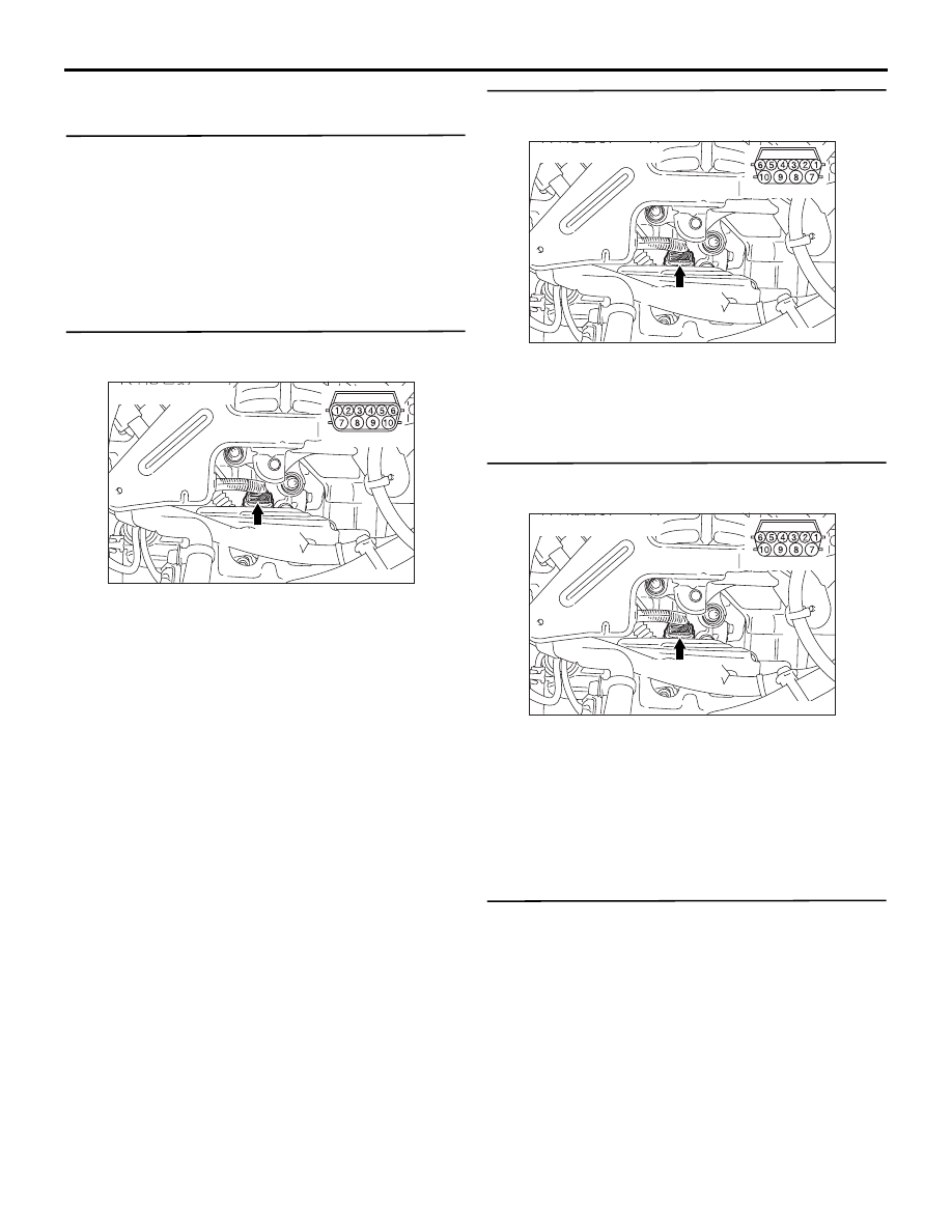
STEP 2. Measure the resistance at A/T control 
solenoid valve assembly connector B-109.

Disconnect the connector, and measure the 
resistance between terminal 1 and 2 at the sensor 
side.

OK: 

• 16.7  20.5 k (at 0°C)

• 7.3  8.9 k (at 20°C)

• 3.4  4.2 k (at 40°C)

• 1.9  2.2 k (at 60°C)

• 1.0  1.2 k (at 80°C)

• 0.57  0.69 k (at 100°C)

Q: Is the check result normal?

YES : 

Go to Step 3.

NO : 

Replace the A/T fluid temperature sensor.

STEP 3. Connector check: B-109 A/T control 
solenoid valve assembly

Check for the contact with terminals.

Q: Is the check result normal?

YES : 

Go to Step 4.

NO : 

Repair the defective connector.

STEP 4. Measure the resistance at A/T control 
solenoid valve assembly connector B-109.

Disconnect the connector, and measure the 
resistance between terminal 2 and earth at the wiring 
harness side.

OK: 2 

 or less

Q: Is the check result normal?

YES : 

Go to Step 9.

NO : 

Go to Step 5.

STEP 5. Measure the voltage at engine-A/T-ECU 
connector C-113.
(1) Connect A/T control solenoid valve assembly 

connector B-109.

AC303628AF

B-109 (GR)

Connector: B-109

Sensor side

AC303628

B-109 (GR)

Harness side

AG

Connector: B-109

AC303628

B-109 (GR)

Harness side

AG

Connector: B-109

TROUBLESHOOTING <A/T>

AUTOMATIC TRANSMISSION (FF)

23A-20

(2) Turn the ignition switch to the ON position.

(3) Measure the voltage between engine-A/T-ECU 

connector C-113 terminal No.96 and earth. 

OK: 0.5 V or less

Q: Is the check result normal?

YES : 

Go to Step 8.

NO : 

Go to Step 6.

STEP 6. Connector check: C-113 engine-A/T-ECU 
connector

Check for the contact with terminals.

Q: Is the check result normal?

YES : 

Go to Step 7.

NO : 

Repair the defective connector.

STEP 7. MUT-III data list

Item 15: A/T fluid temperature sensor (Refer to Data 
List Table 

P.23A-117

). 

Q: Is the check result normal?

YES : 

Intermittent malfunction (Refer to GROUP 

00 

− How to Cope with Intermittent 

Malfunction 

P.00-5

).

NO : 

Replace the engine-A/T-ECU.

AC311284

Engine-A/T-ECU

Harness side

Engine-A/T-ECU

C-113 (GR)

C-113 (GR)

104

93

95

98

92

94

96

97

99

100

91

103
110

111

101

108

109

105

107

106

102

115

117

112

118

116

114 113

120 119

AF

Connector: C-113 <LHD>

Connector: C-113 <RHD>

AC311284

Engine-A/T-ECU

Harness side

Engine-A/T-ECU

C-113 (GR)

C-113 (GR)

104

93

95

98

92

94

96

97

99

100

91

103
110

111

101

108

109

105

107

106

102

115

117

112

118

116

114 113

120 119

AF

Connector: C-113 <LHD>

Connector: C-113 <RHD>

TROUBLESHOOTING <A/T>

AUTOMATIC TRANSMISSION (FF)

23A-21

STEP 8. Connector check: C-113 engine-A/T-ECU 
connector

Check for the contact with terminals.

Q: Is the check result normal?

YES : 

Go to Step 14.

NO : 

Repair the defective connector.

STEP 9. Measure the voltage at A/T control 
solenoid valve assembly connector B-109.

(1) Disconnect the connector, and measure the 

voltage between terminal 1 and earth at the 

wiring harness side.

(2) Turn the ignition switch to the ON position.

OK: 4.5 

 4.9 V

Q: Is the check result normal?

YES : 

Go to Step 7.

NO : 

Go to Step 10.

STEP 10. Measure the voltage at engine-A/T-ECU 
connector C-113.
(1) Connect A/T control solenoid valve assembly 

connector B-109.

(2) Turn the ignition switch to the ON position.

(3) Measure the voltage between engine-A/T-ECU 

connector C-113 terminal No.119 and earth. 

OK: 

• 3.8  4.0 V (at 20°C)

• 3.2  3.4 V (at 40°C)

• 1.7  1.9 V (at 80°C)

Q: Is the check result normal?

YES : 

Go to Step 12.

NO : 

Go to Step 11.

AC311284

Engine-A/T-ECU

Harness side

Engine-A/T-ECU

C-113 (GR)

C-113 (GR)

104

93

95

98

92

94

96

97

99

100

91

103
110

111

101

108

109

105

107

106

102

115

117

112

118

116

114 113

120 119

AF

Connector: C-113 <LHD>

Connector: C-113 <RHD>

AC303628

B-109 (GR)

Harness side

AG

Connector: B-109

AC311284

Engine-A/T-ECU

Harness side

Engine-A/T-ECU

C-113 (GR)

C-113 (GR)

104

93

95

98

92

94

96

97

99

100

91

103
110

111

101

108

109

105

107

106

102

115

117

112

118

116

114 113

120 119

AF

Connector: C-113 <LHD>

Connector: C-113 <RHD>

TROUBLESHOOTING <A/T>

AUTOMATIC TRANSMISSION (FF)

23A-22

STEP 11. Connector check: C-113 
engine-A/T-ECU connector

Check for the contact with terminals.

Q: Is the check result normal?

YES : 

Go to Step 7.

NO : 

Repair the defective connector.

STEP 12. Connector check: C-113 
engine-A/T-ECU connector

Check for the contact with terminals.

Q: Is the check result normal?

YES : 

Go to Step 13.

NO : 

Repair the defective connector.

AC311284

Engine-A/T-ECU

Harness side

Engine-A/T-ECU

C-113 (GR)

C-113 (GR)

104

93

95

98

92

94

96

97

99

100

91

103
110

111

101

108

109

105

107

106

102

115

117

112

118

116

114 113

120 119

AF

Connector: C-113 <LHD>

Connector: C-113 <RHD>

AC311284

Engine-A/T-ECU

Harness side

Engine-A/T-ECU

C-113 (GR)

C-113 (GR)

104

93

95

98

92

94

96

97

99

100

91

103
110

111

101

108

109

105

107

106

102

115

117

112

118

116

114 113

120 119

AF

Connector: C-113 <LHD>

Connector: C-113 <RHD>


Content   ..  836  837  838  839   ..