Mitsubishi Grandis. Manual - part 835


  Index      Mitsubishi     Mitsubishi Grandis - service repair manual


Search            


Content   ..  833  834  835  836   ..


Mitsubishi Grandis. Manual - part 835


TROUBLESHOOTING <A/T>

AUTOMATIC TRANSMISSION (FF)

23A-7

TROUBLESHOOTING <A/T>

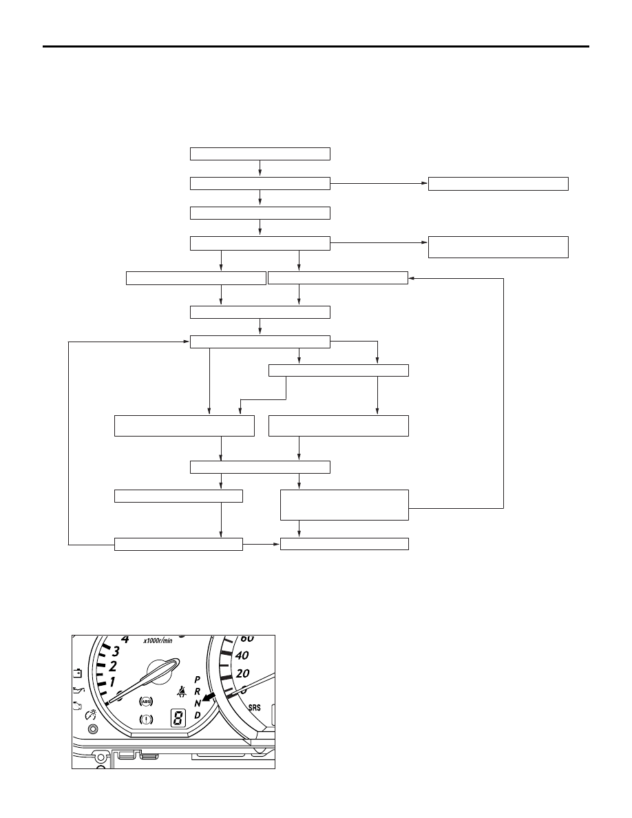
STANDARD FLOW OF DIAGNOSIS 
TROUBLESHOOTING

M1231013500472

DIAGNOSIS FUNCTION

M1231019000237

N RANGE LAMP SYSTEM

If there is a problem with any of the A/T system, the 
N range lamp will flash at a rate of approximately 
once per second.
If the N range lamp is flashing at a rate of 
approximately once per second, check the diagnosis 
output.

N range lamp flashing item

• Input shaft speed sensor system

• Output shaft speed sensor system

• Solenoid valve system

• Non-synchronization at various shift ranges

• A/T control relay system


Ask about trouble symptoms

Check the A/T fluid

Check the trouble symptoms

Replace the A/T fluid

To INSPECTION CHART FOR
TROUBLE SYMPTOMS

Reading of a diagnosis code

Erase of a diagnosis code

Check the trouble symptoms

Inhibitor switch, TPS check

Road test

Recheck diagnosis codes

To INSPECTION CHART FOR
DIAGNOSIS CODES

To INSPECTION CHART FOR
TROUBLE SYMPTOMS

Check for the cause

Repair

Confirmation test (road test)

INTERMITTENT MALFUNCTIONS
(Refer to GROUP 00 - Points to
Note for Intermittent Malfunction)

Completed

NG

OK

Communication with the
MUT-II not possible

Diagnosis code output
exists

No diagnosis code output

Abnormality exists (no diagnosis code output)

Abnormality exists 
(diagnostic trouble 
code output)

No abnormality

Found

Not found

OK

OK

NG

AC212495

NG

Diagnosis code output
exists

No diagnosis code output

Communication with the
MUT-III not possible

AC311593AB

TROUBLESHOOTING <A/T>

AUTOMATIC TRANSMISSION (FF)

23A-8

NOTE: If the "N" range lamp is flushing 
approximately twice per second, the A/T fluid 
temperature is high. (It flushes when the fluid is 
approximately 125

°

C or more and goes off when the 

fluid is approximately 115

°

C or less).

METHOD OF READING THE DIAGNOSIS 
CODE

Use the MUT-III to read the diagnosis code (Refer to 
GROUP 00 

− How to Use 

Troubleshooting/Inspection Service Points 

P.00-5

).

METHOD OF ERASING THE DIAGNOSIS 
CODE

Use the MUT-III to erase the diagnosis code (Refer 
to GROUP 00 

− How to Use 

Troubleshooting/Inspection Service Points 

P.00-5

).

HOW TO INITIALISE A/T LEARNING 
VALUE

M1231022600024

AIM

The use of EEPROM has enabled the A/T learned 
value to be retained even after the battery terminals 
are disconnected. However, the learned value should 
be initialised if the A/T assembly, the engine 
assembly, the valve body assembly or the solenoid 
valves are replaced. The initialization procedure is as 
below:

INITIALIZATOIN PROCEDURE

1. Shift the selector lever to the P range and turn the 

ignition switch to the LOCK (OFF) position. Then, 
connect the MUT-III to the diagnosis connector.

2. Initialize the learned value on the initializaion 

screen.

3. After this initialization, make the system learn the 

idling in accordance with "Learning procedure for 
idling in MPI engine" (Refer to GROUP 00 

− 

Precautions before Service 

P.00-18

).

ROAD TEST

M1231007800485

Proced
ure

Pre-test/opera
tion 
conditions

Test/operation

Judgment value

Check 
item

Diagnosis 
code No.

Inspection 
procedure 
if there is 
an 
abnormalit
y

1

Ignition switch: 
LOCK (OFF) 
position

Ignition switch

(1) ON

Data List No.54

(1) System voltage 

[V]

A/T 
control 
relay

54

A/T control 
relay 
system

TROUBLESHOOTING <A/T>

AUTOMATIC TRANSMISSION (FF)

23A-9

2

Ignition switch: 
ON
Engine: 
Stopped
Selector lever 
position: P

Selector lever 
position

(1) P 
(2) R
(3) N 
(4) D

Data List No.61

(1) P 
(2) R
(3) N 
(4) D

Inhibitor 
switch

27, 28

Inhibitor 
switch 
system

Selector lever 
position

(1) D
(2) Select the sport 

mode

(3) Upshift and hold 

the selector lever 
in that position 
(2nd gear)

(4) Downshift and 

hold the selector 
lever in that 
position (1st gear)

Data List No.67

(1) OFF 
(2) ON
(3) ON
(4) ON

Select 
switch

Sport mode 
switch 
system

Data List No.68

(1) OFF 
(2) OFF
(3) ON
(4) OFF

Upshift 
switch

Data List No.69

(1) OFF 
(2) OFF
(3) OFF 
(4) ON

Downshift 
switch

Shift indicator lamp

(1) Only D 

illuminates

(2) Only 1 

illuminates

(3) Only 2 

illuminates

(4) Only 1 

illuminates

Shift 
indicator 
lamp

Accelerator pedal

(1) Fully closed
(2) Depressed
(3) Fully opened

Data List No.11

(1) 300 

− 700 mV

(2) Gradually 

increases from 
(1)

(3) 4,000 mV or 

more

TPS

TPS 
system

Brake pedal

(1) Depressed
(2) Released

Data List No.26

(1) ON
(2) OFF

Stop lamp 
switch

26

Stop lamp 
switch 
system

3

Ignition switch: 
START

Starting test at P or 
N position

Starting should be 
possible

Starting 
possible/n
ot 
possible

Starting not 
possible

Proced
ure

Pre-test/opera
tion 
conditions

Test/operation

Judgment value

Check 
item

Diagnosis 
code No.

Inspection 
procedure 
if there is 
an 
abnormalit
y

TROUBLESHOOTING <A/T>

AUTOMATIC TRANSMISSION (FF)

23A-10

4

Driving after 
engine has 
warmed up

Drive for 15 minutes 
or more until the A/T 
fluid temperature 
rises to 70 

− 80 °C.

Data List No.15
Gradually rises to 70 
− 80 °C

A/T fluid 
temperatu
re sensor

15, 16

A/T fluid 
temperatur
e sensor 
system

Proced
ure

Pre-test/opera
tion 
conditions

Test/operation

Judgment value

Check 
item

Diagnosis 
code No.

Inspection 
procedure 
if there is 
an 
abnormalit
y


Content   ..  833  834  835  836   ..