Mitsubishi Grandis. Manual - part 767
TROUBLESHOOTING
MULTIPORT FUEL INJECTION (MPI)
13A-319
DIAGNOSIS PROCEDURE
STEP 1. Connector check: C-110 engine-ECU
<M/T> connector or engine-ECU <A/T> or
engine-ECU
Q: Is the check result normal?
YES :
Go to Step 2 .
NO :
Repair or replace.
STEP 2. Check at C-110 engine-ECU <M/T>
connector or engine-A/T-ECU <A/T> connector.
• Disconnect connector, and measure at harness
side.
• Ignition switch: ON
• Short-circuit terminal No. 17 to earth.
OK: Fan motor stops rotating.
Q: Is the check result normal?
YES :
Go to Step 3 .
NO :
Go to Step 4 .
STEP 3. Check the trouble symptoms.
Q: Does trouble symptom persist?
YES :
Replace engine-ECU <M/T> or
engine-A/T-ECU <A/T>.
NO :
Intermittent malfunction (Refer to GROUP
00
− How to Use
Troubleshooting/Inspection Service Points
).
AK305618AB
1
2
3
4
5
6
7
8
9
10
11
12
13
14
15
16
17
18
19
20
21
22
23
24
25
26
27
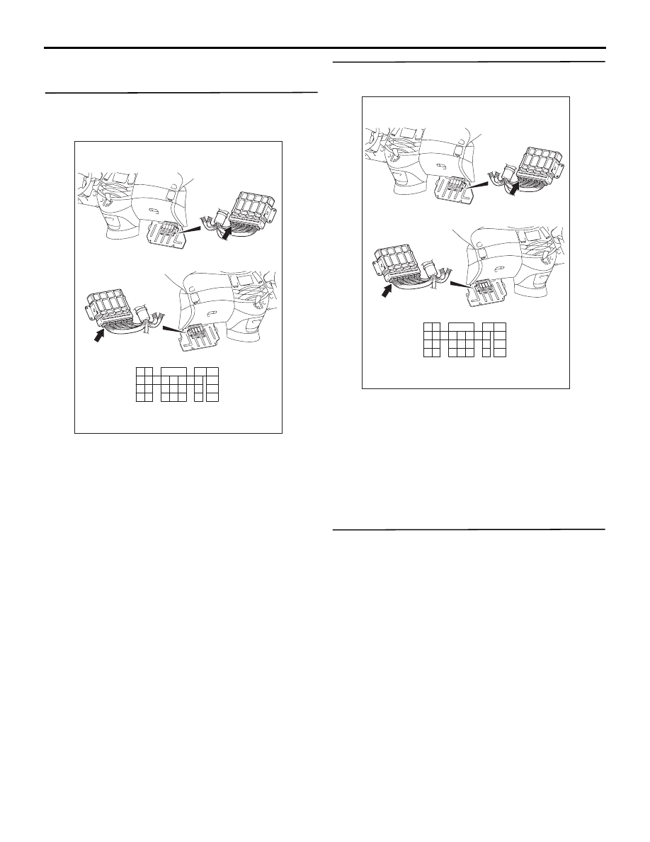
Connector: C-110
<L.H. drive vehicles>
<R.H. drive vehicles>
C-110 (GR)
C-110 (GR)
Harness side connector
AK305618AB
1
2
3
4
5
6
7
8
9
10
11
12
13
14
15
16
17
18
19
20
21
22
23
24
25
26
27
Connector: C-110
<L.H. drive vehicles>
<R.H. drive vehicles>
C-110 (GR)
C-110 (GR)
Harness side connector