Mitsubishi Grandis. Manual - part 745


  Index      Mitsubishi     Mitsubishi Grandis - service repair manual


Search            


Content   ..  743  744  745  746   ..


Mitsubishi Grandis. Manual - part 745


TROUBLESHOOTING

MULTIPORT FUEL INJECTION (MPI)

13A-231

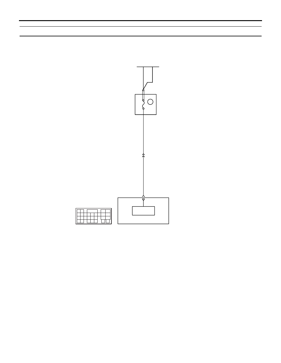
Code No. P1603: Battery Backup Circuit Malfunction

OPERATION

• Power is directly supplied to the engine-ECU 

<M/T> or engine-A/T-ECU <A/T> (terminal No. 
58) from the battery.

FUNCTION

• The engine-ECU <M/T> or engine-A/T-ECU 

<A/T> is check the open circuit of battery backup 
line.

TROUBLE JUDGMENT

Check Conditions

• After engine starting sequence is completed. 

• Battery positive voltage is 10 V or higher. 

Judgment Criterion

• Battery backup line voltage is 6 V or lower for 2 

seconds.

AK305569

31

35363738394041 42 43
444546474849

50 51

5253

545556

57 58

32

33 34

9

AB

Fusible link (26)

W

W

W-G

W-G

58

Battery
backup

Engine-ECU <M/T> or
engine-A/T-ECU <A/T>

3

Wire colour code
B: Black  LG: Light green  G: Green  L: Blue  W: White  Y: Yellow  SB: Sky blue  BR: Brown  O: Orange  GR: Gray
R: Red  P: Pink  V: Violet

20A

Relay
box

Battery backup circuit

A-16

C-111

(MU803803)

TROUBLESHOOTING

MULTIPORT FUEL INJECTION (MPI)

13A-232

PROBABLE CAUSE

• Open/short circuit in battery backup line circuit or 

loose connector contact

• Failed engine-ECU <M/T>

• Failed engine-A/T-ECU <A/T>

DIAGNOSIS PROCEDURE

STEP 1. MUT-III diagnosis code

• Temporarily place the ignition switch in "LOCK" 

(OFF) position, and 10 seconds after that, place it 
in "ON" position again.

Q: Is the diagnosis code P1603 set?

YES : 

Go to Step 2 .

NO : 

Intermittent malfunction (Refer to GROUP 
00 

− How to use Troubleshooting/Inspection 

Service Points 

P.00-5

).

STEP 2. Perform voltage measurement at C-111 
engine-ECU <M/T> connector or engine-A/T-ECU 
<A/T> connector.

• Disconnect connector, and measure at harness 

side.

• Ignition switch: ON

• Voltage between terminal No. 58 and earth.

OK: System voltage

Q: Is the check result normal?

YES : 

Go to Step 3 .

NO : 

Check intermediate connector A-16, and 

repair if necessary. If intermediate 
connector is normal, check and repair 
harness between battery and C-111 
(terminal No. 58) engine-ECU <M/T> 
connector or engine-A/T-ECU <A/T> 
connector.

• Check power supply line for 

open/short circuit.

STEP 3. Check harness between battery and 
C-111 (terminal No. 58) engine-ECU <M/T> 
connector or engine-A/T-ECU <A/T> connector.
NOTE: Before checking harness, check intermediate 
connector A-16, and repair if necessary.

• Check earthing line for damage.

Q: Is the check result normal?

YES : 

Go to Step 4 .

NO : 

Repair or replace.

AK305625AB

Connector: C-111

<L.H. drive vehicles>

<R.H. drive vehicles>

C-111 (GR)

C-111 (GR)

Harness side connector

31

32

33

34

35

36

37

38

39

40

41

42

43

44

45

46

47

48

49

52

53

54

55

56

57

58

50

51

AK305625AB

Connector: C-111

<L.H. drive vehicles>

<R.H. drive vehicles>

C-111 (GR)

C-111 (GR)

Harness side connector

31

32

33

34

35

36

37

38

39

40

41

42

43

44

45

46

47

48

49

52

53

54

55

56

57

58

50

51

TROUBLESHOOTING

MULTIPORT FUEL INJECTION (MPI)

13A-233

STEP 4. Connector check: C-111 engine-ECU 
<M/T> connector or engine-A/T-ECU <A/T> 
connector.

Q: Is the check result normal?

YES : 

Go to Step 5 .

NO : 

Repair or replace.

STEP 5. Check the trouble symptoms.

Q: Does trouble symptom persist?

YES : 

Replace engine-ECU <M/T> or 

engine-A/T-ECU <A/T>.

NO : 

Intermittent malfunction (Refer to GROUP 
00 

− How to Use 

Troubleshooting/Inspection Service 
Points

P.00-5

).

AK305625AB

Connector: C-111

<L.H. drive vehicles>

<R.H. drive vehicles>

C-111 (GR)

C-111 (GR)

Harness side connector

31

32

33

34

35

36

37

38

39

40

41

42

43

44

45

46

47

48

49

52

53

54

55

56

57

58

50

51

TROUBLESHOOTING

MULTIPORT FUEL INJECTION (MPI)

13A-234

Code No. P2100: Throttle Valve Control Servo Circuit (open)

OPERATION

• Controls the current that is applied from the 

engine-ECU <M/T> or engine-A/T-ECU <A/T> 
(terminals No. 133, No. 141) to the 
electronic-controlled throttle valve (terminals No. 
1, No. 2).

FUNCTION

• Engine-ECU <M/T> or engine-A/T-ECU <A/T> 

varies the direction and the amperage of the 
current that is applied to the throttle valve control 
servo in order to control the opening of the 
throttle valve.

TROUBLE JUDGMENT

Check Condition

• Battery positive voltage is 8.3 V or higher.

Judgement Criteria

• Throttle actuator control motor current is 0.1 A or 

less for 0.72 second.

PROBABLE CAUSE

• Failed throttle valve control servo.

• Open/short circuit in throttle valve control servo 

circuit or lose connector contact.

• Failed engine-ECU <M/T>

• Failed engine-A/T-ECU <A/T>

AK305570

6

1 2 3 4 5

121122

123 124

125126127128129 130 131 132 133

134135

136137 138 139 140 141

142143

144

145 146

1 2

3 4

5 6 7

11

10

9

8

AB

133

1

Engine-ECU <M/T> or
engine-A/T-ECU <A/T>

B

R-L

L-Y

B

141

145

144

4

3

11

B

2

B-06

GND

GND

Throttle valve control servo circuit

C-114

(MU803801)

C-115

(MU801850)

Wire colour code
B: Black  LG: Light green  G: Green  L: Blue  W: White  Y: Yellow  SB: Sky blue  BR: Brown  O: Orange  GR: Gray
R: Red  P: Pink  V: Violet

Electronic-controlled
throttle valve


Content   ..  743  744  745  746   ..