Mitsubishi Grandis. Manual - part 743


  Index      Mitsubishi     Mitsubishi Grandis - service repair manual


Search            


Content   ..  741  742  743  744   ..


Mitsubishi Grandis. Manual - part 743


TROUBLESHOOTING

MULTIPORT FUEL INJECTION (MPI)

13A-223

STEP 11. Check and repair harness between 
B-12X (terminal No. 4) throttle valve control servo 
relay connector and battery.

• Check power supply line for damage.

Q:  Is the harness connector in good condition?

YES : 

Go to Step 12 .

NO : 

Intermittent malfunction (Refer to GROUP 
00 

− How to Use 

Troubleshooting/Inspection Service Points 

P.00-5

).

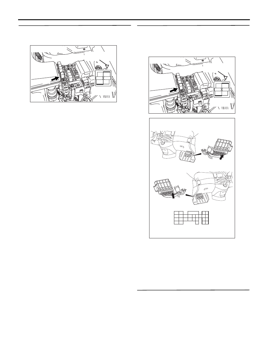
STEP 12. Check and repair harness between 
B-12X (terminal No. 1) throttle valve control servo 
relay connector and C-114 (terminal No. 132) 
engine-ECU <M/T> connector or engine-A/T-ECU 
<A/T> connector.

• Check power supply line for damage.

Q:  Is the harness connector in good condition?

YES : 

Go to Step 13 .

NO : 

Intermittent malfunction (Refer to GROUP 
00 

− How to Use 

Troubleshooting/Inspection Service Points 

P.00-5

).

STEP 13. Check the trouble symptoms.

Q: Does trouble symptom persist?

AK300992

2

1

3

4

AC

 B-12X

Connector: B-12X

Relay box’s 
triangle marks

Harness side
connector

AK300992

2

1

3

4

AC

 B-12X

Connector: B-12X

Relay box’s 
triangle marks

Harness side
connector

AK305623AB

Connector: C-114

<L.H. drive vehicles>

<R.H. drive vehicles>

C-114 (GR)

C-114 (GR)

121

122

123

124

125

126

127

128

129

130

131

132

133

134

135

136

137

138

139

140

141

142

143

144

145

146

Harness side connector

TROUBLESHOOTING

MULTIPORT FUEL INJECTION (MPI)

13A-224

YES : 

Replace engine-ECU <M/T> or 

engine-A/T-ECU <A/T>.

NO : 

Intermittent malfunction (Refer to GROUP 
00 

− How to Use 

Troubleshooting/Inspection Service Points 

P.00-5

).

TROUBLESHOOTING

MULTIPORT FUEL INJECTION (MPI)

13A-225

Code No. P1021: Oil Control Valve Circuit

OPERATION

• Power is supplied to the oil control valve (terminal 

No. 1) from the engine control relay (terminal No. 

1).

1

2

3

4

AK305599

1 2

9192

939495

96979899

100

105

113114

115116117

118119120

106

107108109

110111112

101102103

104

6

11

C-116

J/C (4)

AB

Engine
control
relay

R-W

R-W

P-B

B-15X

Oil control
valve

4

3

1

1

2

95

2

Oil control valve circuit

Battery

W-G

W-G

C-113

(MU803805)

B-07

MU802779

Engine-ECU <M/T> or
engine-A/T-ECU <A/T>

Wire colour code
B: Black  LG: Light green  G: Green  L: Blue  W: White  Y: Yellow  SB: Sky blue  BR: Brown  O: Orange  GR: Gray
R: Red  P: Pink  V: Violet

To engine-ECU <M/T> or
engine-A/T-ECU <A/T>

TROUBLESHOOTING

MULTIPORT FUEL INJECTION (MPI)

13A-226

• The engine-ECU <M/T> or engine-A/T-ECU 

<A/T> (terminal No. 95) makes the power 
transistor in the unit be in ON position, and that 
makes currents go on the oil control valve 
(terminal No. 2).

FUNCTION

• The oil control valve switches the cams to 

operate the MIVEC in the low-speed or 
high-speed mode in accordance with the signals 
from the engine-ECU <M/T> or engine-A/T-ECU 
<A/T>.

TROUBLE JUDGMENT

Check Conditions

• Ignition switch is "ON" position

• Battery positive voltage is higher than 10 V.

• MIVEC operating in the low-speed mode.

Judgment Criteria

• The engine-ECU terminal voltage of oil control 

valve circuit is less than 1.5 V for 2 seconds.

PROBABLE CAUSE

• Failed purge oil control valve

• Open/short circuit in oil control valve circuit or 

loose connector contact

• Failed engine-ECU <M/T>

• Failed engine-A/T-ECU <A/T>

DIAGNOSIS PROCEDURE

STEP 1. Connector check: B-07 oil control valve 
connector

Q: Is the check result normal?

YES : 

Go to Step 2 .

NO : 

Repair or replace.

STEP 2: Perform resistance measurement at B-07 
oil control valve connector.

• Disconnect connector, and measure at control 

valve side.

• Resistance between terminal No. 1 and No. 2.

OK: 6.9 

 7.9  (at 20°C)

Q: Is the check result normal?

YES : 

Go to Step 3 .

NO : 

Replace oil control valve.

STEP 3. Perform voltage measurement at B-07 oil 
control valve connector.

• Disconnect connector, and measure at harness 

side.

• Ignition switch: ON

• Voltage between terminal No. 1 and earth.

OK: System voltage

Q: Is the check result normal?

YES : 

Go to Step 5 .

NO : 

Go to Step 4 .

AK300966

1

2

AC

B-07 (B)

Connector: B-07

Harness side connector

AK300966

1

2

AC

B-07 (B)

Connector: B-07

Harness side connector

AK300966

1

2

AC

B-07 (B)

Connector: B-07

Harness side connector


Content   ..  741  742  743  744   ..