Mitsubishi Grandis. Manual - part 740


  Index      Mitsubishi     Mitsubishi Grandis - service repair manual


Search            


Content   ..  738  739  740  741   ..


Mitsubishi Grandis. Manual - part 740


TROUBLESHOOTING

MULTIPORT FUEL INJECTION (MPI)

13A-211

TROUBLE JUDGMENT

Check Conditions

• Battery positive voltage is 8.3 V or higher.

• Throttle position sensor (main) output voltage is 

0.35 

− 4.8 V.

• Drop of throttle position sensor (main) output 

voltage per 100 milliseconds is 0.04 V or more.

Judgement Criterion

• Throttle position sensor (main) output voltage has 

continued to be above 0.5 V higher than the 
target throttle position sensor (main) voltage for 
0.5 second.

Check Conditions

• Battery positive voltage is 8.3 V or higher.

• Throttle position sensor (main) output voltage is 

0.35 

− 4.8 V.

Judgement Criterion

• Difference between throttle position sensor 

(main) output voltage and target throttle position 
sensor (main) voltage is 1 V or higher for 4 
seconds.

PROBALE CAUSE

• Failed throttle valve return spring.

• Failed throttle valve operation.

• Failed throttle valve control servo.

• Open/short circuit in throttle valve control servo 

connector contact.

• Failed engine-ECU <M/T>.

• Failed engine-A/T-ECU <A/T>.

DIAGNOSIS

STEP 1. MUT-III data list

• Refer to Data List Reference Table 

P.13A-363

.

a. Item 9A: Throttle position sensor (main) mid 

opening learning value 

Q: Is the check result normal?

YES : 

Go to Step 2 .

NO : 

Replace throttle body assembly.

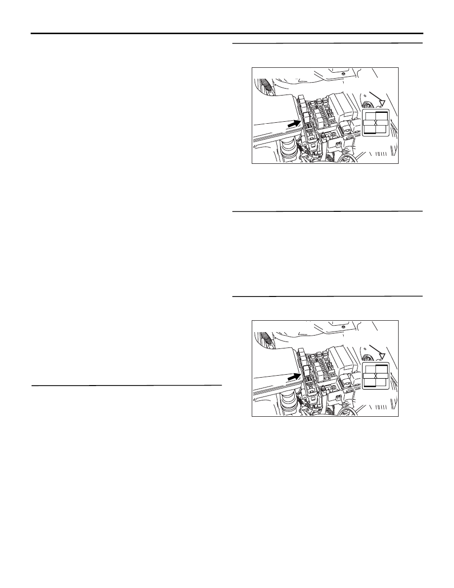
STEP 2. Connector check: B-12X throttle valve 
control servo relay connector

Q: Is the check result normal?

YES : 

Go to Step 3 .

NO : 

Repair or replace.

STEP 3. Check throttle valve control servo relay 
itself.

• Check throttle valve control servo relay (Refer to 

P.13A-394

).

Q: Is the check result normal?

YES : 

Go to Step 4 .

NO : 

Repair.

STEP 4. Perform voltage measurement at B-12X 
throttle valve control servo relay connector.

• Remove relay, and measure at relay box side.

• Voltage between terminal No. 4 and earth.

OK: System voltage

Q: Is the check result normal?

YES : 

Go to Step 5 .

NO : 

Check and repair harness between B-12X 

(terminal No. 4) throttle valve control servo 
relay connector and battery.

• Check power supply line for 

open/short circuit.

AK300992

2

1

3

4

AC

 B-12X

Connector: B-12X

Relay box’s 
triangle marks

Harness side
connector

AK300992

2

1

3

4

AC

 B-12X

Connector: B-12X

Relay box’s 
triangle marks

Harness side
connector

TROUBLESHOOTING

MULTIPORT FUEL INJECTION (MPI)

13A-212

STEP 5. Perform voltage measurement at B-12X 
throttle valve control servo relay connector.

• Remove relay, and measure at relay box side.

• Ignition switch: ON

• Voltage between terminal No. 3 and earth.

OK: System voltage

Q: Is the check result normal?

YES : 

Go to Step 7 .

NO : 

Go to Step 6 .

STEP 6. Connector check: B-15X engine control 
relay connector

Q: Is the check result normal?

YES : 

Check and repair harness between B-15X 

(terminal No. 1) engine control relay 
connector and B-12X (terminal No. 3) 
throttle valve control servo relay connector.

• Check power supply line for 

open/short circuit.

NO : 

Repair or replace.

STEP 7. Perform voltage measurement at C-110 
engine-ECU <M/T> or engine-A/T-ECU <A/T> 
connector.

• Disconnect connector, and measure at harness 

side.

• Ignition switch: ON

• Voltage between terminal No. 15 and earth.

OK: System voltage

Q: Is the check result normal?

YES : 

Go to Step 8 .

NO : 

Check and repair harness between B-12X 

(terminal No. 2) throttle valve control servo 
relay connector and C-110 (terminal No. 15) 
engine-ECU <M/T> connector or 
engine-A/T-ECU <A/T> connector.

• Check earthing line for open/short 

circuit.

AK300992

2

1

3

4

AC

 B-12X

Connector: B-12X

Relay box’s 
triangle marks

Harness side
connector

AK300967

2

1

3

4

AC

Harness side
connector

B-15X

Connector: B-15X

Relay box’s
triangle marks

AK300992

2

1

3

4

AC

 B-12X

Connector: B-12X

Relay box’s 
triangle marks

Harness side
connector

AK305618AB

1

2

3

4

5

6

7

8

9

10

11

12

13

14

15

16

17

18

19

20

21

22

23

24

25

26

27

Connector: C-110

<L.H. drive vehicles>

<R.H. drive vehicles>

C-110 (GR)

C-110 (GR)

Harness side connector

AK300992

2

1

3

4

AC

 B-12X

Connector: B-12X

Relay box’s 
triangle marks

Harness side
connector

TROUBLESHOOTING

MULTIPORT FUEL INJECTION (MPI)

13A-213

STEP 8. Perform voltage measurement at C-114 
engine-ECU <M/T> connector or engine-A/T-ECU 
<A/T> connector.

• Disconnect connector, and measure at harness 

side.

• Ignition switch: ON

• Voltage between terminal No. 132 and earth.

OK: System voltage

Q: Is the check result normal?

YES : 

Go to Step 11 .

NO : 

Go to Step 9 .

STEP 9. Check harness between B-12X (terminal 
No. 1) throttle valve control servo relay 
connector and C-114 (terminal No. 132) 
engine-ECU <M/T> connector or engine-A/T-ECU 
<A/T> connector.

• Check output line for open/short circuit.

Q: Is the check result normal?

YES : 

Go to Step 10 .

NO : 

Repair.

AK305623AB

Connector: C-114

<L.H. drive vehicles>

<R.H. drive vehicles>

C-114 (GR)

C-114 (GR)

121

122

123

124

125

126

127

128

129

130

131

132

133

134

135

136

137

138

139

140

141

142

143

144

145

146

Harness side connector

AK300992

2

1

3

4

AC

 B-12X

Connector: B-12X

Relay box’s 
triangle marks

Harness side
connector

AK305623AB

Connector: C-114

<L.H. drive vehicles>

<R.H. drive vehicles>

C-114 (GR)

C-114 (GR)

121

122

123

124

125

126

127

128

129

130

131

132

133

134

135

136

137

138

139

140

141

142

143

144

145

146

Harness side connector

TROUBLESHOOTING

MULTIPORT FUEL INJECTION (MPI)

13A-214

STEP 10. Check harness between B-15X 
(terminal No. 1) engine control relay connector 
and B-12X (terminal No. 3) throttle valve control 
servo relay connector.

• Check output line for damage.

Q: Is the check result normal?

YES : 

Check and repair harness between B-12X 

(terminal No. 2) throttle valve control servo 
relay connector and C-110 (terminal No. 15) 
engine-ECU <M/T> connector or 
engine-A/T-ECU <A/T> connector.

• Check earthing line for open/short 

circuit.

NO : 

Repair.

STEP 11. Connector check: C-114 and C-110 
engine-ECU <M/T> connector or engine-A/T-ECU 
<A/T> connector

Q: Is the check result normal?

YES : 

Go to Step 12 .

NO : 

Intermittent malfunction (Refer to GROUP 
00 

− How to Use 

Troubleshooting/Inspection Service Points 

P.00-5

).

STEP 12. Check the throttle valve control servo 
itself.

• Check the throttle valve control servo control 

motor itself (Refer to 

P.13A-394

)

Q: Is the check result normal?

YES : 

Go to Step 13 .

NO : 

Replace electronic-controlled throttle valve.

AK300967

2

1

3

4

AC

Harness side
connector

B-15X

Connector: B-15X

Relay box’s
triangle marks

AK300992

2

1

3

4

AC

 B-12X

Connector: B-12X

Relay box’s 
triangle marks

Harness side
connector

AK305618AB

1

2

3

4

5

6

7

8

9

10

11

12

13

14

15

16

17

18

19

20

21

22

23

24

25

26

27

Connector: C-110

<L.H. drive vehicles>

<R.H. drive vehicles>

C-110 (GR)

C-110 (GR)

Harness side connector

AK305624

121

122

123

124

125

126

127

128

129

130

131

132

133

134

135

136

137

138

139

140

141

142

143

144

145

146

1

2

3

4

5

6

7

8

9

10

11

12

13

14

15

16

17

18

19

20

21

22

23

24

25

26

27

<L.H. drive vehicles>

<R.H. drive vehicles>

C-114 (GR)

C-114 (GR)

C-110 (GR)

C-110 (GR)

C-110 Harness side connector

C-114 Harness side connector

Connectors: C-110, C-114

AB


Content   ..  738  739  740  741   ..