Mitsubishi Grandis. Manual - part 729


  Index      Mitsubishi     Mitsubishi Grandis - service repair manual


Search            


Content   ..  727  728  729  730   ..


Mitsubishi Grandis. Manual - part 729


TROUBLESHOOTING

MULTIPORT FUEL INJECTION (MPI)

13A-167

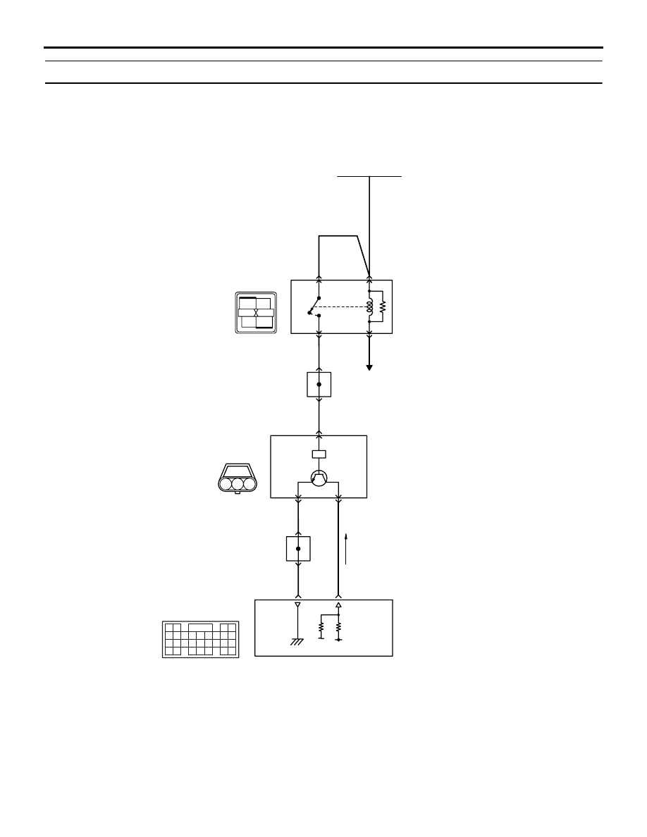
Code No. P0340: Camshaft Position Sensor System

2

1

3

1

2

3

4

61
656667686970 717273
74757677787980 8182
8384

858687

8889

62

6364

AK305562

Engine
control
relay

Camshaft
position
sensor

    B-114
MU802337

71

5 V

1

1

2

2

3

Engine-ECU <M/T>or
engine-A/T-ECU <A/T>

Camshaft position sensor circuit

88

     C-112
(MU803804)

14

12

J/C (4)

C-116

B-W

L-Y

B-W

11

4

J/C (4)

C-116

R-W

R-W

W-G

W-G

Battery

4

3

B-15X

AB

Wire colour code
B: Black  LG: Light green  G: Green  L: Blue  W: White  Y: Yellow  SB: Sky blue  BR: Brown  O: Orange  GR: Gray
R: Red  P: Pink  V: Violet

To engine-ECU <M/T> or
engine-A/T-ECU <A/T>

TROUBLESHOOTING

MULTIPORT FUEL INJECTION (MPI)

13A-168

OPERATION

• Power is supplied to the camshaft position sensor 

(terminal No. 3) from the engine control relay 
(terminal No. 1) and is earthed to the engine-ECU 
<M/T> or engine-A/T-ECU <A/T> (terminal No. 
88) from the camshaft position sensor (terminal 
No. 1).

• A power voltage of 5 V is applied to the camshaft 

position sensor output terminal (terminal No. 2) 
from the engine-ECU <M/T> or engine-A/T-ECU 
<A/T> (terminal No. 71).

FUNCTION

• The camshaft position sensor detects the top 

dead center on the compression stroke of the No. 
1 cylinder and inputs a pulse signal to the 
engine-ECU <M/T> or engine-A/T-ECU <A/T>.

TROUBLE JUDGMENT

Check Condition

• Engine speed is 50 r/min or higher.

Judgment Criterion

• Camshaft position sensor output voltage has not 

been changed (no pulse signal is has been input) 
for 2 seconds.

PROBABLE CAUSE

• Failed camshaft position sensor 

• Open/short circuit in camshaft position sensor 

circuit or loose connector contact

• Failed engine-ECU <M/T>

• Failed engine-A/T-ECU <A/T>

DIAGNOSIS PROCEDURE

STEP 1. Connector check: B-114 camshaft 
position sensor connector

Q: Is the check result normal? 

YES : 

Go to Step 2 .

NO : 

Repair or replace.

STEP 2. Perform voltage measurement at B-114 
camshaft position sensor connector.

• Disconnect connector, and measure at harness 

side.

• Ignition switch: ON 

• Voltage between terminal No. 3 and earth.

OK: System voltage

Q: Is the check result normal? 

YES : 

Go to Step 4 .

NO : 

Go to Step 3 .

STEP 3. Connector check: B-15X engine control 
relay connector

Q: Is the check result normal? 

AK304269

1

2

3

AC

Connector: B-114

B-114 (B)

Harness 
side connector

AK304269

1

2

3

AC

Connector: B-114

B-114 (B)

Harness 
side connector

AK300967

2

1

3

4

AC

Harness side
connector

B-15X

Connector: B-15X

Relay box’s
triangle marks

AK304269

1

2

3

AC

Connector: B-114

B-114 (B)

Harness 
side connector

TROUBLESHOOTING

MULTIPORT FUEL INJECTION (MPI)

13A-169

YES : 

Check intermediate connector C-116, and 

repair if necessary. If intermediate 
connector is normal, check and repair 
harness between B-114 (terminal No. 3) 
camshaft position sensor connector and 
B-15X (terminal No. 1) engine control relay 
connector.

• Check power supply line for 

open/short circuit.

NO : 

Repair or replace.

STEP 4. Perform voltage measurement at B-114 
camshaft position sensor connector.

• Disconnect connector, and measure at harness 

side.

• Ignition switch: ON 

• Voltage between terminal No. 2 and earth.

OK: 4.9 

 5.1 V

Q: Is the check result normal? 

YES : 

Go to Step 10 .

NO : 

Go to Step 5 .

STEP 5. Perform voltage measurement at C-112 
engine-ECU <M/T> connector or engine-A/T-ECU 
<A/T> connector.

• Measure engine-ECU <M/T> or engine-A/T-ECU 

<A/T> terminal voltage.

• Disconnect B-114 camshaft position sensor 

connector.

• Ignition switch: ON 

• Voltage between terminal No. 71 and earth.

OK: 4.9 

 5.1 V

Q: Is the check result normal? 

YES : 

Go to Step 6 .

NO : 

Go to Step 7 .

AK304269

1

2

3

AC

Connector: B-114

B-114 (B)

Harness 
side connector

AK305617

Connector: C-112 

C-112 (GR)

C-112 (GR)

AB

Harness side connector

<R.H. drive vehicles>

<L.H. drive vehicles>

AK304269

1

2

3

AC

Connector: B-114

B-114 (B)

Harness 
side connector

TROUBLESHOOTING

MULTIPORT FUEL INJECTION (MPI)

13A-170

STEP 6. Connector check: C-112 engine-ECU 
<M/T> connector or engine-A/T-ECU <A/T> 
connector

Q: Is the check result normal? 

YES : 

Check and repair harness between B-114 

(terminal No. 2) camshaft position sensor 
connector and C-112 (terminal No. 71) 
engine-ECU <M/T> connector or 
engine-A/T-ECU <A/T> connector. 

• Check output line for open circuit.

NO : 

Repair or replace.

STEP 7. Connector check: C-112 engine-ECU 
<M/T> connector or engine-A/T-ECU <A/T> 
connector

Q: Is the check result normal? 

YES : 

Go to Step 8 .

NO : 

Repair or replace.

AK305617

Connector: C-112 

C-112 (GR)

C-112 (GR)

AB

Harness side connector

<R.H. drive vehicles>

<L.H. drive vehicles>

AK304269

1

2

3

AC

Connector: B-114

B-114 (B)

Harness 
side connector

AK305617

Connector: C-112 

C-112 (GR)

C-112 (GR)

AB

Harness side connector

<R.H. drive vehicles>

<L.H. drive vehicles>


Content   ..  727  728  729  730   ..