Mitsubishi Grandis. Manual - part 728


  Index      Mitsubishi     Mitsubishi Grandis - service repair manual


Search            


Content   ..  726  727  728  729   ..


Mitsubishi Grandis. Manual - part 728


TROUBLESHOOTING

MULTIPORT FUEL INJECTION (MPI)

13A-163

STEP 14. Perform output wave pattern 
measurement at B-121 crank angle sensor 
intermediate connector (Using an oscilloscope).

• Use special tool test harness (MB991658) to 

connect connector, and measure at pick-up 
harness.

• Engine: Idling

• Transmission: Neutral <M/T> or P range <A/T>

• Voltage between terminal No. 2 and earth.

OK: Waveforms should be displayed on 
Inspection procedure using an oscilloscope 
(Refer to 

P.13A-378

), its maximum value 

should be 4.8 V or more, and its minimum 
value should be 0.6 V or less with no noise in 
waveform.

Q: Is the check result normal? 

YES : 

Go to Step 8 .

NO : 

Go to Step 15 .

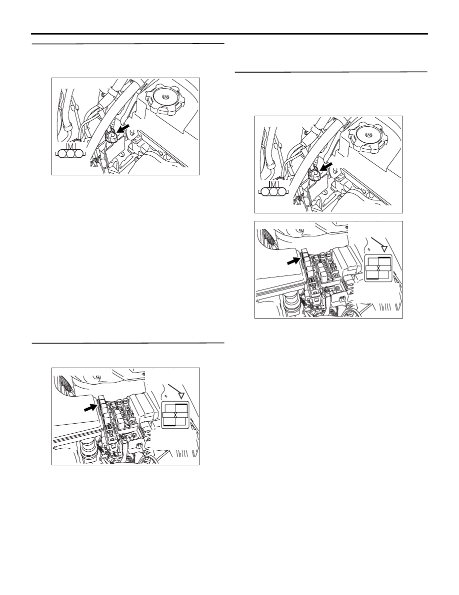
STEP 15. Connector check: B-15X engine control 
relay connector

Q: Is the check result normal? 

YES : 

Go to Step 16 .

NO : 

Repair or replace.

STEP 16. Check harness between B-121 (terminal 
No. 1) crank angle sensor intermediate connector 
and B-15X (terminal No. 1) engine control relay 
connector.

NOTE: Before checking harness, check intermediate 
connector C-116, and repair if necessary. 

• Check power supply line for damage.

Q: Is the check result normal? 

YES : 

Go to Step 17 .

NO : 

Repair.

AK304267

1

2

3

B-121 (GR)

AC

Connector: B-121

Harness 
side connector

AK300967

2

1

3

4

AC

Harness side
connector

B-15X

Connector: B-15X

Relay box’s
triangle marks

AK304267

1

2

3

B-121 (GR)

AC

Connector: B-121

Harness 
side connector

AK300967

2

1

3

4

AC

Harness side
connector

B-15X

Connector: B-15X

Relay box’s
triangle marks

TROUBLESHOOTING

MULTIPORT FUEL INJECTION (MPI)

13A-164

STEP 17. Connector check: C-112 engine-ECU 
<M/T> connector or engine-A/T-ECU <A/T> 
connector

Q: Is the check result normal? 

YES : 

Go to Step 18 .

NO : 

Repair or replace.

STEP 18. Check harness between B-121 (terminal 
No. 2) crank angle sensor intermediate connector 
and C-112 (terminal No. 70) engine-ECU <M/T> 
connector or engine-A/T-ECU <A/T> connector.

• Check output line for damage.

Q: Is the check result normal? 

YES : 

Go to Step 19 .

NO : 

Repair.

AK305617

Connector: C-112 

C-112 (GR)

C-112 (GR)

AB

Harness side connector

<R.H. drive vehicles>

<L.H. drive vehicles>

AK304267

1

2

3

B-121 (GR)

AC

Connector: B-121

Harness 
side connector

AK305617

Connector: C-112 

C-112 (GR)

C-112 (GR)

AB

Harness side connector

<R.H. drive vehicles>

<L.H. drive vehicles>

TROUBLESHOOTING

MULTIPORT FUEL INJECTION (MPI)

13A-165

STEP 19. Check harness between B-121 (terminal 
No. 3) crank angle sensor intermediate connector 
and C-112 (terminal No. 88) engine-ECU <M/T> 
connector or engine-A/T-ECU <A/T> connector.

NOTE: Before checking harness, check intermediate 
connector C-116, and repair if necessary.

• Check earthing line for damage.

Q: Is the check result normal? 

YES : 

Go to Step 20 .

NO : 

Repair. 

STEP 20. Connector check: B-121-1 crank angle 
sensor connector

Q: Is the check result normal? 

YES : 

Go to Step 21 .

NO : 

Repair or replace.

STEP 21. Check harness between B-121 crank 
angle sensor intermediate connector and B-121-1 
crank angle sensor connector.

• Check power supply line open/short circuit and 

damage.

• Check output line for open/short circuit and 

damage.

• Check earthing line for open/short circuit and 

damage.

Q: Is the check result normal? 

YES : 

Go to Step 22 .

NO : 

Replace the timing belt cover.

AK304267

1

2

3

B-121 (GR)

AC

Connector: B-121

Harness 
side connector

AK305617

Connector: C-112 

C-112 (GR)

C-112 (GR)

AB

Harness side connector

<R.H. drive vehicles>

<L.H. drive vehicles>

AK304268

1

2

3

AC

Connector: B-121-1

B-121-1 (B)

Harness 
side connector

AK304267

1

2

3

B-121 (GR)

AC

Connector: B-121

Harness 
side connector

AK304268

1

2

3

AC

Connector: B-121-1

B-121-1 (B)

Harness 
side connector

TROUBLESHOOTING

MULTIPORT FUEL INJECTION (MPI)

13A-166

STEP 22. Check the crankshaft sensing blade.

Q: Is the check result normal? 

YES : 

Go to Step 23 .

NO : 

Replace the crankshaft sensing blade.

STEP 23: MUT-III data list

• Refer to Data List Reference Table 

P.13A-363

.

a. Item 22: Crank angle sensor 

Q: Is the check result normal? 

YES : 

Intermittent malfunction (Refer to GROUP 

00 

− How to Use 

Troubleshooting/Inspection Service Points 

P.00-5

).

NO : 

Replace crank angle sensor.


Content   ..  726  727  728  729   ..