Mitsubishi Grandis. Manual - part 722


  Index      Mitsubishi     Mitsubishi Grandis - service repair manual


Search            


Content   ..  720  721  722  723   ..


Mitsubishi Grandis. Manual - part 722


TROUBLESHOOTING

MULTIPORT FUEL INJECTION (MPI)

13A-139

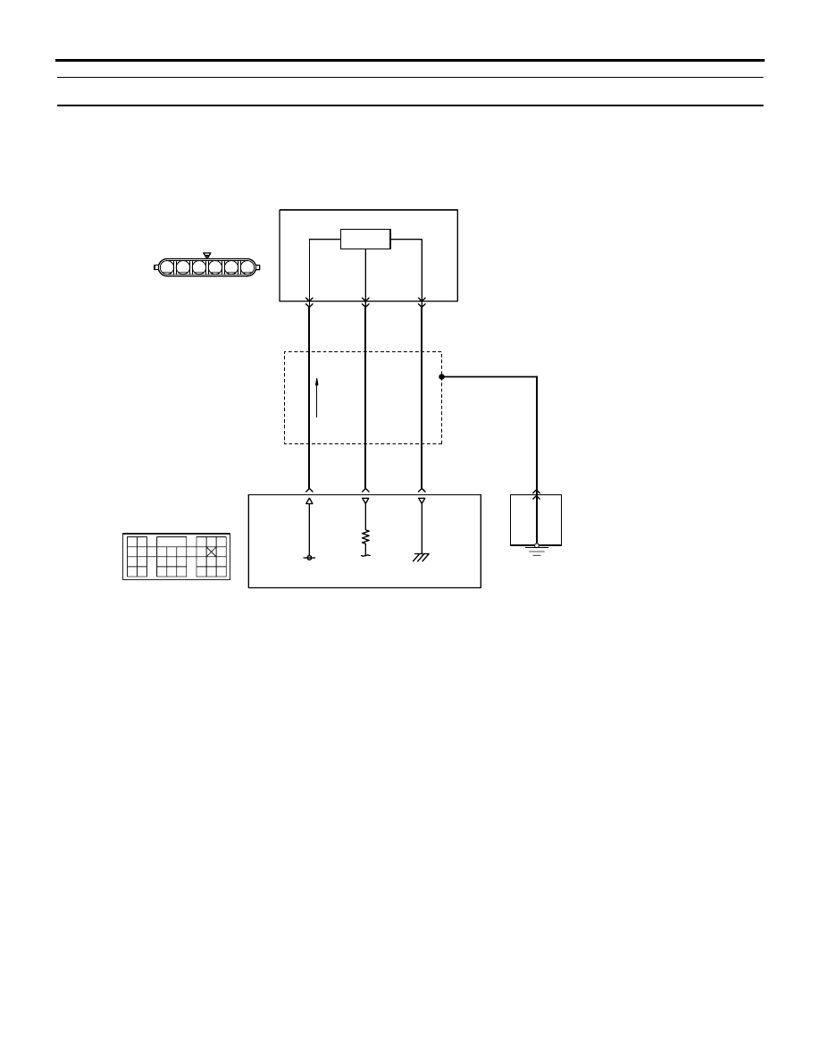
Code No. P0223: Throttle Position Sensor  (Sub) Circuit High Input

OPERATION

• A power voltage of 5 V is applied to the 

electronic-controlled throttle valve (terminal No. 
5) from the engine-ECU <M/T> or 
engine-A/T-ECU <A/T> (terminal No. 106).

• The power voltage is earthed to the engine-ECU 

<M/T> or engine-A/T-ECU <A/T> (terminal No. 
105) from the electronic-controlled throttle valve 
(terminal No. 3).

• The sensor signal is inputted to the engine-ECU 

<M/T> or engine-A/T-ECU <A/T> (terminal No. 
113) from the electronic-controlled throttle valve 
output terminal (terminal No. 6).

FUNCTION

• The throttle position sensor converts the throttle 

valve position into voltage and inputs it into the 
engine-ECU <M/T> or engine-A/T-ECU <A/T>.

• The engine-ECU <M/T> or engine-A/T-ECU 

<A/T> controls the throttle valve position.

TROUBLE JUDGMENT

Check Condition

• Ignition switch is in "ON" position.

Judgment Criterion

• Throttle position sensor (sub) output voltage is 

4.8 V or more for 0.5 second.

PROBABLE CAUSE

• Failed throttle position sensor (sub)

AK305560

6

1 2 3 4 5

9192

939495

96979899

100

105

113114

115116117

118119120

106

107108109

110111112

101102103

104

(sub)

Hall IC

AB

5 V

106

5

B

C-115

W

B

R

Engine-ECU <M/T> or
engine-A/T-ECU <A/T>

113

105

7

6

3

Throttle position sensor (sub) circuit

B-06

C-113

(MU803805)

Wire colour code
B: Black  LG: Light green  G: Green  L: Blue  W: White  Y: Yellow  SB: Sky blue  BR: Brown  O: Orange  GR: Gray
R: Red  P: Pink  V: Violet

Electronic-controlled
throttle valve

TROUBLESHOOTING

MULTIPORT FUEL INJECTION (MPI)

13A-140

• Open/short circuit in throttle position sensor (sub) 

circuit or loose connector contact

• Failed engine-ECU <M/T>

• Failed engine-A/T-ECU <A/T>

DIAGNOSIS PROCEDURE

STEP 1. MUT-III data list

• Refer to Data List Reference Table 

P.13A-363

.

a. Item 14: Throttle position sensor (sub)

Q: Is the check result normal?

YES : 

Intermittent malfunction (Refer to GROUP 

00 

− How to Use 

Troubleshooting/Inspection Service Points 

P.00-5

).

NO : 

Go to Step 2 .

STEP 2. Connector check: B-06 
electronic-controlled throttle valve connector

Q: Is the check result normal?

YES : 

Go to Step 3 .

NO : 

Repair or replace.

STEP 3. Perform resistance measurement at B-06 
electronic-controlled throttle valve connector.

• Disconnect connector, and measure at harness 

side.

• Resistance between terminal No. 3 and earth.

OK: 2 

 or less

Q: Is the check result normal?

YES : 

Go to Step 7 .

NO : 

Go to Step 4 .

STEP 4. Connector check: C-113 engine-ECU 
<M/T> connector or engine-A/T-ECU <A/T> 
connector

Q: Is the check result normal?

YES : 

Go to Step 5 .

NO : 

Repair or replace.

AK300972

1

6 5 4 3 2

AC

Harness side connector

Connectors: B-06

B-06 (B)

AK300972

1

6 5 4 3 2

AC

Harness side connector

Connectors: B-06

B-06 (B)

AK305616AB

Connector: C-113

<L.H. drive vehicles>

<R.H. drive vehicles>

C-113 (GR)

C-113 (GR)

91

92

93

94

95

96

97

98

99

100

101

102

103

104

105

106

107

108

109

110

111

112

113

114

115

116

117

118

119

120

Harness side connector

TROUBLESHOOTING

MULTIPORT FUEL INJECTION (MPI)

13A-141

STEP 5. Check harness between B-06 (terminal 
No. 3) electronic-controlled throttle valve 
connector and C-113 (terminal No. 105) 
engine-ECU <M/T> connector or engine-A/T-ECU 
<A/T> connector.

• Check earthing line for open circuit and damage.

Q: Is the check result normal?

YES : 

Go to Step 6 .

NO : 

Repair.

STEP 6. MUT-III data list

• Refer to Data List Reference Table 

P.13A-363

.

a. Item 14: Throttle position sensor (sub)

Q: Is the check result normal?

YES : 

Intermittent malfunction (Refer to GROUP 

00 

− How to Use 

Troubleshooting/Inspection Service Points 

P.00-5

).

NO : 

Replace engine-ECU <M/T> or 
engine-A/T-ECU <A/T>.

STEP 7. Replace the electronic-controlled 
throttle valve

• After replacing the electronic-controlled throttle 

valve, re-check the trouble symptoms.

Q: Is the check result normal?

YES : 

Check end.

NO : 

Replace engine-ECU <M/T> or 
engine-A/T-ECU <A/T>.

Code No. P0300: Random/Multiple Cylinder Misfire Detected

OPERATION

• Refer to Code No. P0201: No. 1 injector system 

P.13A-115

.

• Refer to Code No. P0202: No. 2 injector system 

P.13A-120

.

• Refer to Code No. P0203: No. 3 injector system 

P.13A-125

.

• Refer to Code No. P0204: No. 4 injector system 

P.13A-130

.

FUNCTION

• If a misfire occurs while the engine is running, the 

engine speed changes for an instant.

• The engine-ECU <M/T> or engine-A/T-ECU 

<A/T> checks for such changes in engine speed.

AK300972

1

6 5 4 3 2

AC

Harness side connector

Connectors: B-06

B-06 (B)

AK305616AB

Connector: C-113

<L.H. drive vehicles>

<R.H. drive vehicles>

C-113 (GR)

C-113 (GR)

91

92

93

94

95

96

97

98

99

100

101

102

103

104

105

106

107

108

109

110

111

112

113

114

115

116

117

118

119

120

Harness side connector

TROUBLESHOOTING

MULTIPORT FUEL INJECTION (MPI)

13A-142

TROUBLE JUDGMENT

Check Conditions

• Engine speed is 500 − 6,500 r/min.

• Engine coolant temperature is −10°C or higher.

• Barometric pressure is 76 kPa or higher.

• Volumetric efficiency is between 30% and 55 %.

• Adaptive learning is complete for the vane which 

generates a crankshaft position signal.

• While the engine is running, excluding gear 

shifting, deceleration, sudden 
acceleration/deceleration and A/C compressor 
switching.

• The throttle deviation is −0.06 V/10 ms to +0.06 

V/10 ms.

Judgment Criteria (change in the angular 

acceleration of the crankshaft is used for 
misfire detection).

• Misfire has occurred more frequently than the 

limit during the last 200 revolutions (when the 
catalyst temperature has been 950

°C or higher).

Or

• Misfire has occurred 15 times or more in the last 

1,000 revolutions (that has been equivalent to 
approximately 1.5 times the emission standard).

PROBABLE CAUSE

• Ignition system related part(s) failed

• Failed crank angle sensor

• Incorrect air-fuel ratio

• Low compression pressure

• Failed engine coolant temperature sensor

• Skipping of timing belt teeth.

• EGR system and EGR valve failed

• Failed engine-ECU <M/T>

• Failed engine-A/T-ECU <A/T>

DIAGNOSIS PROCEDURE

STEP 1.MUT-III data list 

• Item 22: Crank angle sensor

OK: Keep the engine speed constant to make 
the pulse width of output waveform 
constant.

Q: Is the check result normal?

YES : 

Go to Step 2 .

NO : 

Check crank angle sensor system (Refer to 
Code No. P0335 

P.13A-157

).

STEP 2. MUT-III data list

• Refer to Data List Reference Table 

P.13A-363

.

a. Item 21: Engine coolant temperature sensor
b. Item 81: Long-term fuel compensation

c. Item 82: Short-term fuel compensation

Q: Are the check results normal?

YES : 

 Go to Step 3 .

NO : 

Perform the diagnosis code classified check 
procedure for the sensor that has shown an 
abnormal data valve (Refer to Inspection 
Chart for Diagnosis Code 

P.13A-20

).

STEP 3. Check ignition coil spark.

Q: Is the check result normal?

YES : 

 Go to Step 4 .

NO : 

Check ignition circuit system (Refer to 
Inspection Procedure 26 

P.13A-355

).

STEP 4. Connector check: Injector connector

a. B-101 (No. 1 injector connector)
b. B-102 (No. 2 injector connector)

c. B-104 (No. 3 injector connector)

d. B-105 (No. 4 injector connector)

Q: Are the check results normal?

YES : 

Go to Step 5 .

NO : 

Repair or replace.

STEP 5. Check injector itself. 

• Check Injector itself (Refer to 

P.13A-393

).

Q: Is the check result normal?

YES : 

 Go to Step 6 .

NO : 

Replace injector.

STEP 6. Fuel pressure measurement.

• Fuel pressure measurement (Refer to Fuel 

Pressure Test 

P.13A-383

)

Q: Is the check result normal?

YES : 

 Go to Step 7 .

NO : 

Repair.

AK300978

M

1

2

AG

Harness side connector

Connectors: B-101, B-102, B-104, B-105

B-101 (GR) B-102 (GR)

B-105 (GR)

B-104 (GR)


Content   ..  720  721  722  723   ..