Mitsubishi Grandis. Manual - part 706


  Index      Mitsubishi     Mitsubishi Grandis - service repair manual


Search            


Content   ..  704  705  706  707   ..


Mitsubishi Grandis. Manual - part 706


TROUBLESHOOTING

MULTIPORT FUEL INJECTION (MPI)

13A-75

YES : 

Check and repair harness between B-23 

(terminal No. 4) cylinder 1, 4 oxygen sensor 
(rear) connector and C-113 (terminal No. 
117) engine-ECU <M/T> connector or 
engine-A/T-ECU <A/T> connector.

• Check output line for open circuit.

NO : 

Repair or replace.

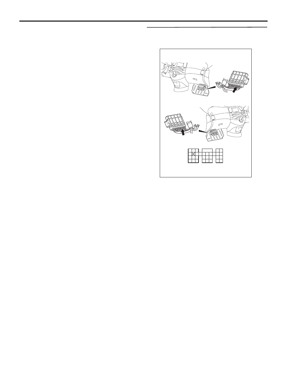
STEP 12. Connector check: C-113 engine-ECU 
<M/T> connector or engine-A/T-ECU <A/T> 
connector

Q: Is the check result normal?

YES : 

Go to Step 6 .

NO : 

Repair or replace.

AK305616AB

Connector: C-113

<L.H. drive vehicles>

<R.H. drive vehicles>

C-113 (GR)

C-113 (GR)

91

92

93

94

95

96

97

98

99

100

101

102

103

104

105

106

107

108

109

110

111

112

113

114

115

116

117

118

119

120

Harness side connector

TROUBLESHOOTING

MULTIPORT FUEL INJECTION (MPI)

13A-76

Code No. P0141: Cylinder 1, 4 Oxygen Sensor (Rear) Heater System

OPERATION

• Power is supplied to the heater power terminal 

(terminal No. 1) of the cylinder 1, 4 oxygen 
sensor (rear) connector from the engine control 
relay (terminal No. 1).

• The heater (terminal No. 3) of the cylinder 1, 4 

oxygen sensor (rear) connector is controlled by 
the power transistor in the engine-ECU <M/T> or 
engine-A/T-ECU <A/T> (terminal No. 24).

FUNCTION

• The power supply to the cylinder 1, 4 oxygen 

sensor (rear) heater is controlled by the ON/OFF 
control of the power transistor in the engine-ECU 
<M/T> or engine-A/T-ECU <A/T>.

• Heating the cylinder 1, 4 oxygen sensor (rear) 

heater enables the cylinder 1, 4 oxygen sensor 
(rear) to provide good response even when the 
exhaust emission temperature is low.

AK305554

1

2

3

4

1

2

3

5

6 7 8 9

4

20

21 22

232425

2627

10111213

14 15

16 1718

19

1

2

3

4

AB

4

3

1

2

Cylinder 1, 4 oxygen sensor (rear)

1

2

3

4

Engine-ECU <M/T> or
engine-A/T-ECU <A/T>

24

Engine
control
relay

W-G

R-W

R-W

G-W

W-G

Battery

B-15X

C-110

(MU803802)

Cylinder 1,4 oxygen sensor (rear) heater circuit

Wire colour code
B: Black  LG: Light green  G: Green  L: Blue  W: White  Y: Yellow  SB: Sky blue  BR: Brown  O: Orange  GR: Gray
R: Red  P: Pink  V: Violet

B-23

MU802605

J/C (4)
C-116

To engine-ECU <M/T> or
engine-A/T-ECU <A/T>

11

7

To engine-ECU <M/T> or
engine-A/T-ECU <A/T>

TROUBLESHOOTING

MULTIPORT FUEL INJECTION (MPI)

13A-77

TROUBLE JUDGMENT

Check Conditions

• 60 seconds have elapsed since the previous 

monitoring started.

• Engine coolant temperature is 20°C or higher.

• While cylinder 1, 4 oxygen sensor (rear) heater is 

on.

• Battery positive voltage is 11 − 16 V.

Judgment Criterion

• Cylinder 1, 4 oxygen sensor (rear) heater 

currents have continued to be 0.16 A or lower, or 
5.0 A or higher for 4 seconds.

PROBABLE CAUSE

• Failed cylinder 1, 4 oxygen sensor (rear) heater

• Open/short circuit in cylinder 1, 4 oxygen sensor 

(rear) heater circuit or loose connector contact

• Failed engine-ECU <M/T>

• Failed engine-A/T-ECU <A/T>

DIAGNOSIS PROCEDURE

STEP 1. Connector check: B-23 cylinder 1, 4 
oxygen sensor (rear) connector

Q: Is the check result normal?

YES : 

Go to Step 2 .

NO : 

Repair or replace.

STEP 2. Perform resistance measurement at B-23 
cylinder 1, 4 oxygen sensor (rear) connector.

• Disconnect connector, and measure at sensor 

side.

• Resistance between terminal No. 1 and No. 3.

OK: 11 

 18 

Q: Is the check result normal?

YES : 

Go to Step 3 .

NO : 

Replace cylinder 1, 4 oxygen sensor (rear).

AK300975

1

2

3

4

AC

B-23 (B)

Connector: B-23

Harness side
connector

Cylinder 1, 4 oxygen
sensor (rear)

AK300975

1

2

3

4

AC

B-23 (B)

Connector: B-23

Harness side
connector

Cylinder 1, 4 oxygen
sensor (rear)

TROUBLESHOOTING

MULTIPORT FUEL INJECTION (MPI)

13A-78

STEP 3. Perform voltage measurement at B-23 
cylinder 1, 4 oxygen sensor (rear) connector.

• Disconnect connector, and measure at harness 

side.

• Ignition switch: ON

• Voltage between terminal No. 1 and earth.

OK: System voltage

Q: Is the check result normal?

YES : 

Go to Step 5 .

NO : 

Go to Step 4 .

STEP 4. Connector check: B-15X engine control 
relay connector

Q: Is the check result normal?

YES : 

Check intermediate connector C-116, and 

repair if necessary. If intermediate 
connector is normal, check and repair 
harness between B-23 (terminal No. 1) 
cylinder 1, 4 oxygen sensor (rear) connector 
and B-15X (terminal No. 1) engine control 
relay connector.

• Check power supply line for 

open/short circuit.

NO : 

Repair or replace.

AK300975

1

2

3

4

AC

B-23 (B)

Connector: B-23

Harness side
connector

Cylinder 1, 4 oxygen
sensor (rear)

AK300967

2

1

3

4

AC

Harness side
connector

B-15X

Connector: B-15X

Relay box’s
triangle marks

AK300975

1

2

3

4

AC

B-23 (B)

Connector: B-23

Harness side
connector

Cylinder 1, 4 oxygen
sensor (rear)


Content   ..  704  705  706  707   ..