Mitsubishi Grandis. Manual - part 704


  Index      Mitsubishi     Mitsubishi Grandis - service repair manual


Search            


Content   ..  702  703  704  705   ..


Mitsubishi Grandis. Manual - part 704


TROUBLESHOOTING

MULTIPORT FUEL INJECTION (MPI)

13A-67

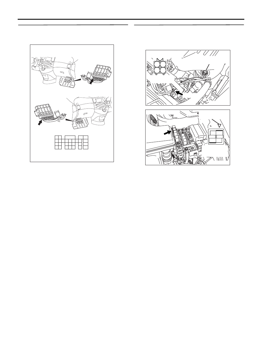
STEP 8. Connector check: C-110 engine-ECU 
<M/T> connector or engine-A/T-ECU <A/T> 
connector

Q: Is the check result normal?

YES : 

Go to Step 9 .

NO : 

Repair or replace.

STEP 9. Check harness between B-22 (terminal 
No. 1)cylinder 1, 4 oxygen sensor (front) 
connector and B-15X (terminal No. 1) engine 
control relay connector.

NOTE: Before checking harness check intermediate 
connector C-116, and repair if necessary. 

• Check power supply line for damage.

Q: Is the check result normal?

YES : 

Go to Step 10 .

NO : 

Repair.

AK305618AB

1

2

3

4

5

6

7

8

9

10

11

12

13

14

15

16

17

18

19

20

21

22

23

24

25

26

27

Connector: C-110

<L.H. drive vehicles>

<R.H. drive vehicles>

C-110 (GR)

C-110 (GR)

Harness side connector

AK300973

1

2

3

4

AB

ƒn![ƒlƒX‘¤

ƒRƒlƒNƒ^![

B-24 (

"•)

ƒRƒlƒNƒ^![

ƒRƒlƒNƒ^![: B-24

Harness side
connector

B-22 (GR)

Connector: B-22

Cylinder 1, 4 oxygen
sensor (front)

AC

AK300967

2

1

3

4

AC

Harness side
connector

B-15X

Connector: B-15X

Relay box’s
triangle marks

TROUBLESHOOTING

MULTIPORT FUEL INJECTION (MPI)

13A-68

STEP 10. Check harness between B-22 (terminal 
No. 3) cylinder 1, 4 oxygen sensor (front) 
connector and C-110 (terminal No. 25) 
engine-ECU <M/T> connector or engine-A/T-ECU 
<A/T> connector.

• Check earthing line for damage.

Q: Is the check result normal?

YES : 

Go to Step 11 .

NO : 

Repair.

STEP 11. Check the trouble symptoms.

Q: Does trouble symptom persist?

YES : 

Replace engine-ECU <M/T> or 

engine-A/T-ECU <A/T>.

NO : 

Intermittent malfunction (Refer to GROUP 
00 

− How to Use 

Troubleshooting/Inspection Service Points 

P.00-5

).

AK300973

1

2

3

4

AB

ƒn![ƒlƒX‘¤

ƒRƒlƒNƒ^![

B-24 (

"•)

ƒRƒlƒNƒ^![

ƒRƒlƒNƒ^![: B-24

Harness side
connector

B-22 (GR)

Connector: B-22

Cylinder 1, 4 oxygen
sensor (front)

AC

AK305618AB

1

2

3

4

5

6

7

8

9

10

11

12

13

14

15

16

17

18

19

20

21

22

23

24

25

26

27

Connector: C-110

<L.H. drive vehicles>

<R.H. drive vehicles>

C-110 (GR)

C-110 (GR)

Harness side connector

TROUBLESHOOTING

MULTIPORT FUEL INJECTION (MPI)

13A-69

Code No. P0136: Cylinder 1, 4 Oxygen Sensor (Rear) System

OPERATION

• The sensor signal is inputted to the engine-ECU 

<M/T> or engine-A/T-ECU <A/T> (terminal No. 
117) from the cylinder 1, 4 oxygen sensor (rear) 
output terminal (terminal No. 4).

• The cylinder 1, 4 oxygen sensor (rear) (terminal 

No. 2) is earthed with engine-ECU <M/T> or 
engine-A/T-ECU <A/T> (terminal No. 96).

FUNCTION

• The cylinder 1, 4 oxygen sensor (rear) converts 

the concentration of oxygen in the exhaust 
emission into a voltage and inputs the signal to 
the engine-ECU <M/T> or engine-A/T-ECU 
<A/T>.

• When the air-fuel ratio is richer than the 

theoretical air-fuel ratio, the cylinder 1, 4 oxygen 
sensor (rear) outputs a voltage of about 1 V. 
When it is leaner than the theoretical air-fuel 
ratio, it outputs a voltage of about 0 V.

• Based on this signal, the engine-ECU <M/T> or 

engine-A/T-ECU <A/T> corrects the deviation in 
the signal that is output by the cylinder 1, 4 
oxygen sensor (rear).

TROUBLE JUDGMENT

Check Conditions

• Above 3 minutes later after the engine has 

started up.

• The engine coolant temperature is approx. 82°C 

or higher.

• The engine speed is 1200 r/min or more.

• The monitoring time is 5 seconds.

AK305553

9192

939495

96979899

100

105

113114

115116117

118119120

106

107108109

110111112

101102103

104

1

2

3

4

Cylinder 1, 4 oxygen
sensor (rear)

AB

Cylinder 1, 4 oxygen sensor (rear) circuit

Engine-ECU <M/T> or
engine-A/T-ECU <A/T>

B

V

P

From engine control relay

1

2

3

4

96

117

     B-23
MU802605

C-113

(MU803805)

Wire colour code
B: Black  LG: Light green  G: Green  L: Blue  W: White  Y: Yellow  SB: Sky blue  BR: Brown  O: Orange  GR: Gray
R: Red  P: Pink  V: Violet

To engine-ECU <M/T> or
engine-A/T-ECU <A/T>

5

C-115

TROUBLESHOOTING

MULTIPORT FUEL INJECTION (MPI)

13A-70

Judgment Criteria

• When the cylinder 1, 4 oxygen sensor (rear) 

output voltage is 0.2V or less and a power 
voltage of 5 V is applied to the cylinder 1, 4 
oxygen sensor (rear) in the engine-ECU <M/T> 
or engine-A/T-ECU <A/T>, the sensor output 
voltage is 4.5 V or more.

• To be monitored once per driving cycle.

Check Conditions

• 2 seconds later after lack of circuit continuity is 

detected.

• When the front oxygen sensor is normally 

operated.

Judgment Criteria

• When the air-fuel ratio is rich, the cylinder 1, 4 

oxygen sensor (front) output voltage is 0.5 V or 
more.

• The cylinder 1, 4 oxygen sensor (rear) output 

voltage is less than 0.1 V.

• The maximum and maximum of the cylinder 1, 4 

oxygen sensor (rear) output is 0.078 V or less.

PROBABLE CAUSE

• Failed cylinder 1, 4 oxygen sensor (rear)

• Open/short circuit in cylinder 1, 4 oxygen sensor 

(rear) circuit or loose connector contact

• Failed engine-ECU <M/T>

• Failed engine-A/T-ECU <A/T>

DIAGNOSIS PROCEDURE

STEP 1. MUT-III data list

• Refer to Data List Reference Table 

P.13A-363

.

a. Item 59: Cylinder 1, 4 oxygen sensor (rear)

Q: Is the check result normal?

YES : 

Intermittent malfunction (Refer to GROUP 

00 

− How to Use 

Troubleshooting/Inspection Service Points 

P.00-5

).

NO : 

Go to Step 2 .

STEP 2. Connector check: B-23 cylinder 1, 4 
oxygen sensor (rear) connector

Q: Is the check result normal?

YES : 

Go to Step 3 .

NO : 

Repair or replace.

AK300975

1

2

3

4

AC

B-23 (B)

Connector: B-23

Harness side
connector

Cylinder 1, 4 oxygen
sensor (rear)


Content   ..  702  703  704  705   ..