Mitsubishi Grandis. Manual - part 703


  Index      Mitsubishi     Mitsubishi Grandis - service repair manual


Search            


Content   ..  701  702  703  704   ..


Mitsubishi Grandis. Manual - part 703


TROUBLESHOOTING

MULTIPORT FUEL INJECTION (MPI)

13A-63

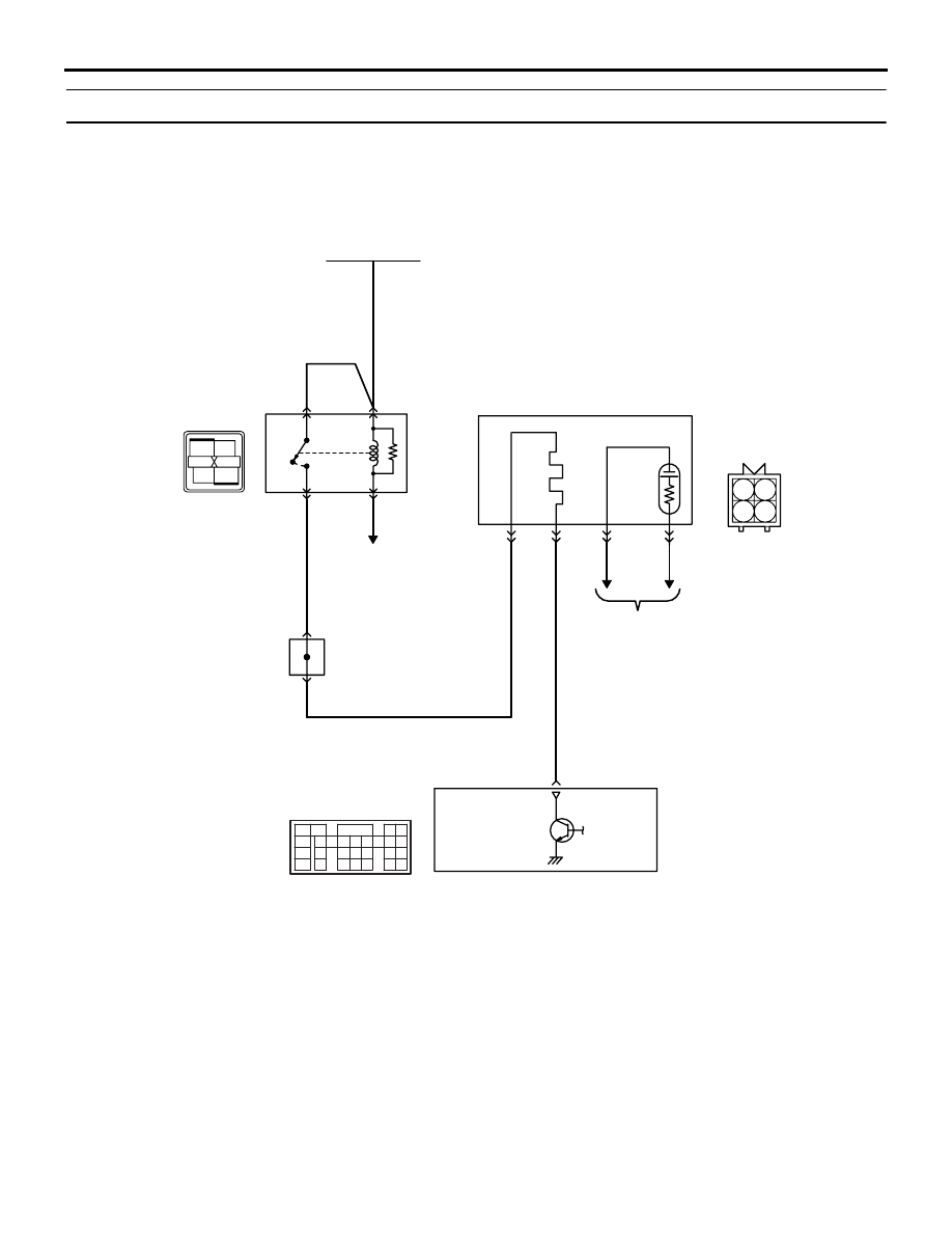
Code No. P0135: Cylinder 1, 4 Oxygen Sensor (Front) Heater System

OPERATION

• Power is supplied to the heater power terminal 

(terminal No. 1) of the Cylinder 1, 4 oxygen 
sensor (front) connector from the engine control 
relay (terminal No. 1).

• The heater (terminal No. 3) of the Cylinder 1, 4 

oxygen sensor (front) connector is controlled by 
the power transistor in the engine-ECU <M/T> or 
engine-A/T-ECU <A/T> (terminal No. 25).

FUNCTION

• The power supply to the cylinder 1, 4 oxygen 

sensor (front) heater is controlled by the ON/OFF 
control of the power transistor in the engine-ECU 
<M/T> or engine-A/T-ECU <A/T>.

• Heating the cylinder 1, 4 oxygen sensor (front) 

heater enables the cylinder 1, 4 oxygen sensor 
(front) to provide good response even when the 
exhaust emission temperature is low.

AK305552

1

2

3

4

1

2

3

5

6 7 8 9

4

20

21 22

232425

2627

10111213

14 15

16 1718

19

1

2

3

4

AB

4

3

1

2

Cylinder 1, 4 oxygen sensor (front)

1

2

3

4

Engine-ECU <M/T> or
engine-A/T-ECU <A/T>

25

Engine
control
relay

W-G

R-W

R-W

P-L

W-G

Battery

B-15X

C-110

(MU803802)

B-22

MU802665

Cylinder 1, 4 oxygen sensor (front) heater circuit

Wire colour code
B: Black  LG: Light green  G: Green  L: Blue  W: White  Y: Yellow  SB: Sky blue  BR: Brown  O: Orange  GR: Gray
R: Red  P: Pink  V: Violet

To engine-ECU <M/T> or
engine-A/T-ECU <A/T>

J/C (4)

11

7

C-116

To engine-ECU <M/T> or
engine-A/T-ECU <A/T>

TROUBLESHOOTING

MULTIPORT FUEL INJECTION (MPI)

13A-64

TROUBLE JUDGMENT

Check Conditions

• 60 seconds have elapsed since the previous 

monitoring started.

• Engine coolant temperature is 20°C or higher.

• While cylinder 1, 4 oxygen sensor (front) heater is 

on.

• Battery positive voltage is 11 − 16 V.

Judgment Criterion

• Cylinder 1, 4 oxygen sensor (front) heater current 

has continued to be 0.16 A or lower, or 7.5 A or 
higher for 4 seconds.

PROBABLE CAUSE

• Failed cylinder 1, 4 oxygen sensor (front) heater

• Open/short circuit in cylinder 1, 4 oxygen sensor 

(front) circuit or loose connector contact

• Failed engine-ECU <M/T>

• Failed engine-A/T-ECU <A/T>

DIAGNOSIS PROCEDURE

STEP 1. Connector check: B-22 cylinder 1, 4 
oxygen sensor (front) connector

Q: Is the check result normal?

YES : 

Go to Step 2 .

NO : 

Repair or replace.

STEP 2. Perform resistance measurement at B-22 
cylinder 1, 4 oxygen sensor (front) connector.

• Disconnect connector, and measure at sensor 

side.

• Resistance between terminal No. 1 and No. 3.

OK: 4.5 

 8.0 

Q: Is the check result normal?

YES : 

Go to Step 3 .

NO : 

Replace cylinder 1, 4 oxygen sensor (front).

STEP 3. Perform voltage measurement at B-22 
cylinder 1, 4 oxygen sensor (front) connector.

• Disconnect connector, and measure at harness 

side.

• Ignition switch: ON

• Voltage between terminal No. 1 and earth.

OK: System voltage

Q: Is the check result normal?

YES : 

Go to Step 5 .

NO : 

Go to Step 4 .

AK300973

1

2

3

4

AB

ƒn![ƒlƒX‘¤

ƒRƒlƒNƒ^![

B-24 (

"•)

ƒRƒlƒNƒ^![

ƒRƒlƒNƒ^![: B-24

Harness side
connector

B-22 (GR)

Connector: B-22

Cylinder 1, 4 oxygen
sensor (front)

AC

AK300973

1

2

3

4

AB

ƒn![ƒlƒX‘¤

ƒRƒlƒNƒ^![

B-24 (

"•)

ƒRƒlƒNƒ^![

ƒRƒlƒNƒ^![: B-24

Harness side
connector

B-22 (GR)

Connector: B-22

Cylinder 1, 4 oxygen
sensor (front)

AC

AK300973

1

2

3

4

AB

ƒn![ƒlƒX‘¤

ƒRƒlƒNƒ^![

B-24 (

"•)

ƒRƒlƒNƒ^![

ƒRƒlƒNƒ^![: B-24

Harness side
connector

B-22 (GR)

Connector: B-22

Cylinder 1, 4 oxygen
sensor (front)

AC

TROUBLESHOOTING

MULTIPORT FUEL INJECTION (MPI)

13A-65

STEP 4. Connector check: B-15X engine control 
relay connector

Q: Is the check result normal?

YES : 

Check intermediate connector C-116, and 

repair if necessary. If intermediate 
connector is normal, check and repair 
harness between B-22 (terminal No. 1) 
cylinder 1, 4 oxygen sensor (front) 
connector and B-15X (terminal No. 1) 
engine control relay connector.

• Check power supply line for 

open/short circuit.

NO : 

Repair or replace.

STEP 5. Perform voltage measurement at C-110 
engine-ECU <M/T> connector or engine-A/T-ECU 
<A/T> connector.

• Measure engine-ECU <M/T> or engine-A/T-ECU 

<A/T> terminal voltage.

• Ignition switch: ON

• Voltage between terminal No. 25 and earth.

OK: System voltage

Q: Is the check result normal?

YES : 

Go to Step 8 .

NO : 

Go to Step 6 .

AK300967

2

1

3

4

AC

Harness side
connector

B-15X

Connector: B-15X

Relay box’s
triangle marks

AK300973

1

2

3

4

AB

ƒn![ƒlƒX‘¤

ƒRƒlƒNƒ^![

B-24 (

"•)

ƒRƒlƒNƒ^![

ƒRƒlƒNƒ^![: B-24

Harness side
connector

B-22 (GR)

Connector: B-22

Cylinder 1, 4 oxygen
sensor (front)

AC

AK305618AB

1

2

3

4

5

6

7

8

9

10

11

12

13

14

15

16

17

18

19

20

21

22

23

24

25

26

27

Connector: C-110

<L.H. drive vehicles>

<R.H. drive vehicles>

C-110 (GR)

C-110 (GR)

Harness side connector

TROUBLESHOOTING

MULTIPORT FUEL INJECTION (MPI)

13A-66

STEP 6. Connector check: C-110 engine-ECU 
<M/T> connector or engine-A/T-ECU <A/T> 
connector

Q: Is the check result normal?

YES : 

Go to Step 7 .

NO : 

Repair or replace.

STEP 7. Check harness between B-22 (terminal 
No. 3) cylinder 1, 4 oxygen sensor (front) 
connector and C-110 (terminal No. 25) 
engine-ECU <M/T> connector or engine-A/T-ECU 
<A/T> connector.

• Check earthing line for open/short circuit.

Q: Is the check result normal?

YES : 

Replace engine-ECU <M/T> or 

engine-A/T-ECU <A/T>.

NO : 

Repair.

AK305618AB

1

2

3

4

5

6

7

8

9

10

11

12

13

14

15

16

17

18

19

20

21

22

23

24

25

26

27

Connector: C-110

<L.H. drive vehicles>

<R.H. drive vehicles>

C-110 (GR)

C-110 (GR)

Harness side connector

AK300973

1

2

3

4

AB

ƒn![ƒlƒX‘¤

ƒRƒlƒNƒ^![

B-24 (

"•)

ƒRƒlƒNƒ^![

ƒRƒlƒNƒ^![: B-24

Harness side
connector

B-22 (GR)

Connector: B-22

Cylinder 1, 4 oxygen
sensor (front)

AC

AK305618AB

1

2

3

4

5

6

7

8

9

10

11

12

13

14

15

16

17

18

19

20

21

22

23

24

25

26

27

Connector: C-110

<L.H. drive vehicles>

<R.H. drive vehicles>

C-110 (GR)

C-110 (GR)

Harness side connector


Content   ..  701  702  703  704   ..