Mitsubishi Grandis. Manual - part 686


  Index      Mitsubishi     Mitsubishi Grandis - service repair manual


Search            


Content   ..  684  685  686  687   ..


Mitsubishi Grandis. Manual - part 686


ON-VEHICLE SERVICE

FUEL SUPPLY

13B-4

2. Remove the rear scuff plate (Refer to GROUP 

52A, Trim Removal and Installation 

P.52A-10

), 

and turn up the floor mat.

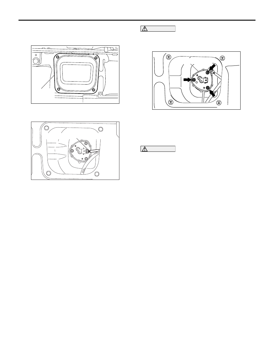
3. Remove the rear floor fuel gauge maintenance 

hole cover (RH).

4. Disconnect the fuel tank gauge unit connector.

CAUTION

When withdrawing the fuel tank gauge unit from 
the service hole, be careful not damage the 
gauge and the float.

5. Remove the fuel tank gauge unit mounting nuts 

and remove the fuel tank gauge unit from service 
hole.

6. Replace the fuel tank gauge unit gasket with a 

new one.

CAUTION

When installing the fuel tank gauge unit into the 
fuel tank via the service hole, be careful not to 
damage the gauge and the float.
7. Install the fuel tank gauge unit into the fuel tank 

via the service hole, and tighten the mounting 
nuts.

8. Connect the fuel tank gauge unit connector.
9. Install the rear floor fuel gauge maintenance hole 

cover (RH).

10.Return the floor mat and install the rear scuff 

plate. (Refer to GROUP 52A, Trim Removal and 
Installation 

P.52A-10

).

11.Install the rail cover inner, the rail cover outer and 

the second seat assembly. (Refer to GROUP 52A, 
Second Seat Assembly Removal and Installation 

P.52A-26

).

AC301331

AC

Rear floor
fuel gauge
maintenance hole cover

AC301291AC

Fuel tank gauge unit connector

AC301328

AC301328

AC

Fuel tank gauge unit

FUEL TANK

FUEL SUPPLY

13B-5

FUEL TANK

REMOVAL AND INSTALLATION

M1135001900605

Pre-removal Operation
• Fuel Line Pressure Reduction [Refer to GROUP 13A, 

On-vehicle Service 

− Fuel Relay Disconnection (How to 

Reduce Pressurized Fuel Lines) 

P.13A-386

].

• Draining Fuel

• Centre Exhaust Pipe Removal (Refer to GROUP 15, 

Exhaust Pipe and Main Muffler 

P.15-9

).

Post-installation Operation
• Centre Exhaust Pipe Installation (Refer to GROUP 15, 

Exhaust Pipe and Main Muffle

P.15-9

).

• Refilling Fuel

• Checking for Fuel Leaks

AC301915AB

1

N

2

3

4

5

6

7

8

10

9

12

11

11

12

12

13

14

15

16

17

18

19

20

21

22

23

24

25

26

27

N

AC301915

Fuel tank assembly removal 
steps

1.

Fuel filler hose connection <Fuel 
filler neck side>

2.

Fuel filler neck breather hose 
connection <Fuel filler neck side>

3.

Rear under cover (LH)

4.

Rear under cover (RH)

5.

Wiring harness clamp connection

6.

Rear ABS sensor (LH) connector 

7.

Rear ABS sensor (RH) connector

<<A>>

>>C<<

8.

Fuel high-pressure hose 
connection

9.

Fuel tank hose (vapour) connection

10. Fuel tank hose (return) connection 
11. Connector clamp connection

<<B>>

12. Wiring harness clamp connection

<<B>>

13. Fuel tank pump and gauge 

assembly connector connection

<<B>>

14. Fuel tank gauge unit connector 

connection

Fuel tank assembly removal 
steps (Continued)

FUEL TANK

FUEL SUPPLY

13B-6

<<B>>

Fuel tank assembly

15. Fuel high-pressure hose
16. Fuel tank hose (return)
17. Fuel tank hose (vapour)
18. Fuel filler neck hose
19. Fuel filler neck breather hose
20. Fuel pump bracket plat

<<C>>

>>B<<

21. Fuel tank pump and gauge 

assembly

22. Fuel tank pump gasket 

<<C>>

>>A<<

23. Fuel tank gauge unit
24. Fuel tank gauge unit gasket
25. Fuel tank clamp
26. Fuel tank lower protector
27. Fuel tank

Fuel tank assembly removal 
steps (Continued)

AC310533AB

32

31

30

29

28

1

2

<FUEL FILLER NECK>

Fuel filler neck removal steps

1.

Fuel filler hose connection <Fuel 
filler neck side>

2.

Fuel filler neck breather hose 
connection <Fuel filler neck side>

28. Fuel filler hose protector

Rear suspension crossmember 
stay (LH) (Refer to GROUP 34 - 
Rear suspension ceossmember 

P.34-11

)

29. Fuel tank cap
30. Fuel filler neck assembly
31. Fuel filler neck gasket
32. Fuel filler neck valve

Fuel filler neck removal steps 

FUEL TANK

FUEL SUPPLY

13B-7

REMOVAL SERVICE POINTS
<<A>> FUEL HIGH-PRESSURE HOSE 
DISCONNECTION

1. Push up the double lock of the fuel high-pressure 

hose connector.

2. Disconnect the fuel high-pressure hose while 

pushing the double lock of the fuel high-pressure 
hose connector.

<<B>> WIRING HARNESS CLAMP 
CONNECTION/FUEL TANK PUMP AND 
GAUGE ASSEMBLY CONNECTOR 
CONNECTION/FUEL TANK GAUGE UNIT 
CONNECTOR CONNECTION/FUEL TANK 
ASSEMBLY REMOVAL

CAUTION

Be careful not to open circuit in the wiring 
harness when removing the fuel tank assembly.

1. Raise and support the fuel tank assembly with a 

transmission jack, and remove the mounting nuts.

2. Use a transmission jack while taking care of the 

wiring harness, and  lower the fuel tank assembly 
until the wiring harness installation position of  fuel 
tank assembly's top can be made sure. 

3. Remove the each wiring harness clamp 

connection, fuel tank pump and gauge assembly 
connector connection and fuel tank gauge unit 
connector connection, and then remove the fuel 
tank assembly.

<<C>> FUEL TANK PUMP AND GAUGE 
ASSEMBLY/FUEL TANK GAUGE UNIT 
REMOVEL

CAUTION

When withdrawing the fuel tank pump and gauge 
assembly and the fuel tank gauge unit from the 
fuel tank, be careful not to damage the gauge and 
the float.
Disconnect the suction hose from the fuel tank assist 
pump while withdrawing the fuel tank pump and 
gauge assembly from the fuel tank.

INSTALLATION SERVICE POINS
>>A<< FUEL TANK GAUGE UNIT 
INSTALLATION

CAUTION

When installing the fuel tank gauge unit into the 
fuel tank, be careful not to damage the gauge and 
the float.

AC207382 AC

Double lock of the connector

Fuel line pipe

Fuel high-pressure hose

AC207383AC

Lock of the connector

Fuel line pipe

Fuel high-pressure hose

AC310541

AB

Wiring harness

Fuel tank assembly

AC302908 AC

AC302908

Fuel tank pump 
and gauge 
assembly

Fuel tank assist pump

Suction hose


Content   ..  684  685  686  687   ..