Mitsubishi Grandis. Manual - part 652
HOW TO USE THIS MANUAL
ENGINE OVERHAUL
11B-3
ENGINE OVERHAUL
11-54
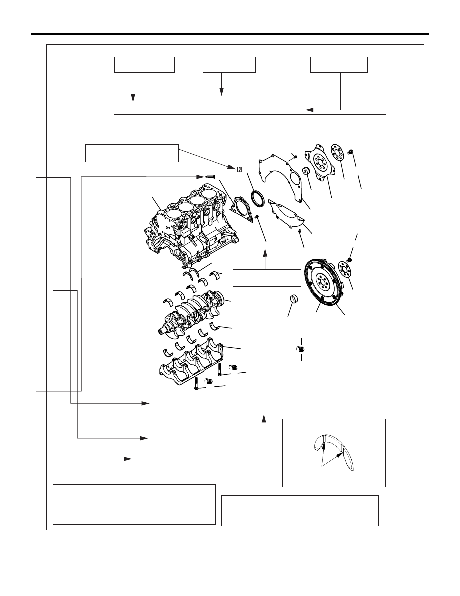
CRANKSHAFT AND CYLINDER BLOCK
REMOVAL AND INSTALLATION
Section title
Page number
Procedures and cautions for removal, instal-
lation, disassembly, and reassembly are ex-
plained under this category of heading.
The alphabetical character in this category of
heading matches that of the relevant removal
steps, installation steps, disassembly steps, or
reassembly steps.
Denotes non-reusable part.
Tightening torque
CRANKSHAFT AND CYLINDER BLOCK
Removal steps
1.
Flywheel bolt
2. Adapter plate
3.
Flywheel
4. Crankshaft bushing
5.
Drive plate bolt
6.
Adapter plate
7.
Drive plate
8.
Crankshaft bushing
9.
Rear plate
10.
Bell housing cover
>>E<< 11.
Oil seal case
>>D<< 12.
Oil seal
>>A<< THRUST BEARING INSTALLATION
INSTALLATION SERVICE POINTS
AK100786AB
Grooves
Group title
AK303970
AK303794AB
6
7
8
9
10
11
12
14
13
15
16
17
18
19
20
11 ± 1 N·m
132 ± 5 N·m
25 ± 2 N·m
Apply engine oil
to all moving
parts before
installation.
5
9.0 ± 1.0 N·m
11 ± 1 N·m
→ + 90˚
25 ± 2 N·m
→ + 90˚
1
3
A
4
2
132 ± 5 N·m