Mitsubishi Grandis. Manual - part 629
 

  Index      Mitsubishi     Mitsubishi Grandis - service repair manual


Search            


Content   ..  627  628  629  630   ..


Mitsubishi Grandis. Manual - part 629


DIAGNOSIS

CONTROLLER AREA NETWORK (CAN)

54D-614

TROUBLE JUDGMENT

If the MUT-III can not received signal from the 
steering wheel angle sensor, CAN bus line 
connector(s) are broken or an open circuit has 
occurred.

COMMENTS ON TROUBLE SYMPTOM

The CAN bus line wiring harness wire or connectors 
may have loose, corroded, or damaged terminals, or 
terminals pushed back in the connector, or the 
steering wheel angle sensor may be defective.

POSSIBLE CAUSES

• Damaged harness wires and connectors

• Malfunction of the steering wheel angle sensor

DIAGNOSTIC PROCEDURE

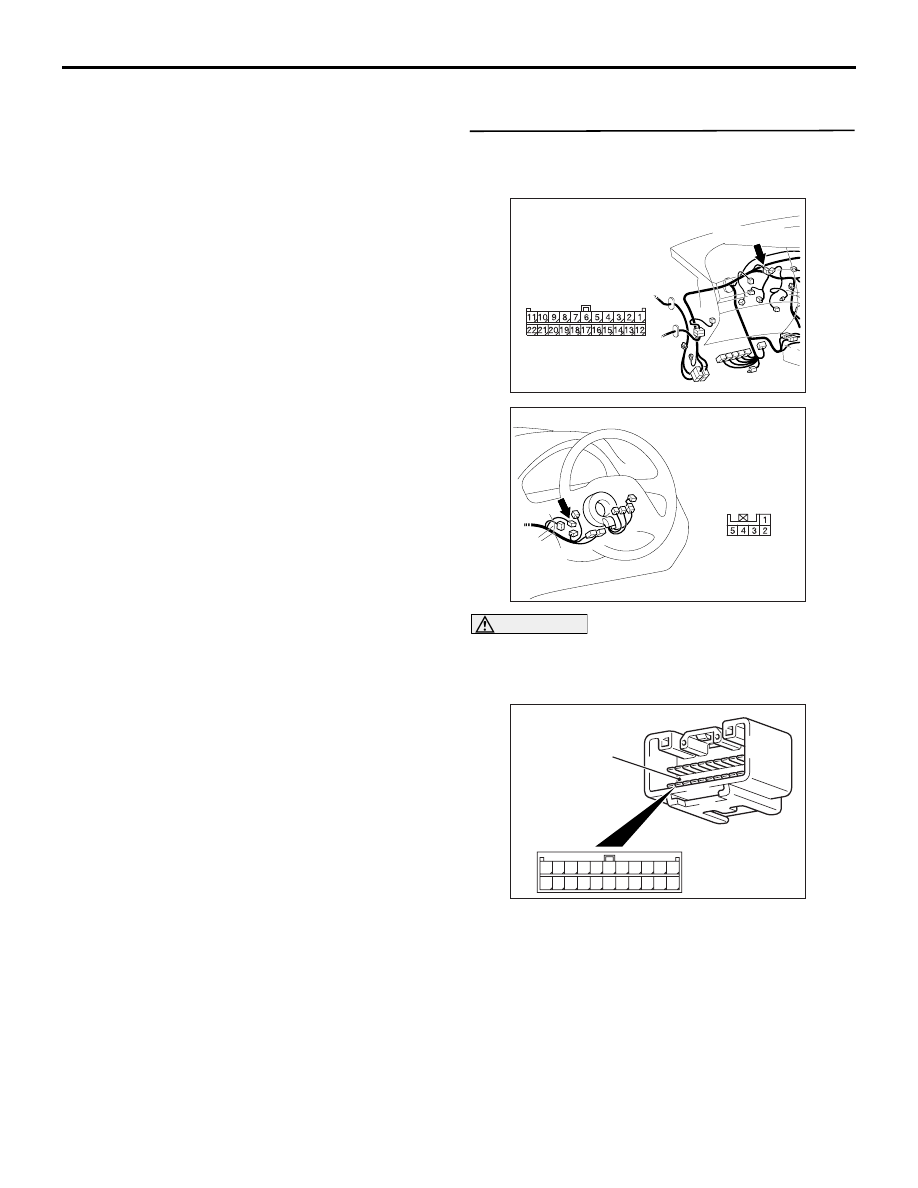
STEP 1. Connector check: C-09 joint connector 
(CAN2) connector and C-306 steering wheel 
angle sensor connector

CAUTION

The strand end of the twist wire should be within 
10 cm from the connector. For details refer to 

P.54D-8

.

When checking the joint connector, ensure that its 
wiring harness side and its short pins are not 
damaged.

Q: Are the check result normal?

YES : 

Go to Step 2 .

NO : 

Repair a defective connector or replace the 
joint connector.

AC310628AY

Connector: C-09 <RHD>

C-09 (GR)

Harness side

AC310183

AF

Connector: C-306 <RHD>

Harness side

AC209350

1

12

2

13

3

14

4

15

5

16

6

17

7

18

8

19

9

20

10

21

11

22

AB

Short pin

DIAGNOSIS

CONTROLLER AREA NETWORK (CAN)

54D-615

STEP 2. Resistance measurement at C-09 joint 
connector (CAN2) and C-306 steering wheel 
angle sensor connector.

CAUTION

A digital multimeter should be used. For details 
refer to 

P.54D-8

.

CAUTION

The test wiring harness should be used. For 
details refer to 

P.54D-8

.

(1) Disconnect the joint connector (CAN2) and the 

steering wheel angle sensor connector, and 
measure at the wiring harness side.

(2) Ignition switch: OFF (LOCK)

CAUTION

When measuring the resistance, disconnect the 
negative battery terminal. For details refer to 

P.54D-8

.

(3) Ensure that the negative battery terminal is 

disconnected.

(4) Continuity between C-09 joint connector (CAN2) 

terminal No.3 and C-306 steering wheel angle 
sensor connector terminal No.3

OK: 2 ohms or less

(5) Continuity between C-09 joint connector (CAN2) 

terminal No.14 and C-306 steering wheel angle 

AC310628AY

Connector: C-09 <RHD>

C-09 (GR)

Harness side

AC310183

AF

Connector: C-306 <RHD>

Harness side

AC204582

Harness side: C-09

EH

Harness side: C-306

Test 
harness

Test 
harness

AC204582

Harness side: C-09

EG

Harness side: C-306

Test 
harness

Test 
harness

ENGINE COMPARTMENT RELAY BOX DISASSEMBLY AND REASSEMBLY

CONTROLLER AREA NETWORK (CAN)

54D-616

sensor connector terminal No.4

OK: 2 ohms or less

CAUTION

Strictly observe the specified wiring harness 
repair procedure. For details refer to 

P.54D-8

.

Q: Are the check result normal?

YES : 

<All the resistances measure 2 

Ω or less> 

Power supply to the steering wheel angle 
sensor may be suspected. Diagnose the 
ASC system. Refer to 

P.35C-135

.

NO : 

<Either or all of the voltages measure more 
than 2 

Ω> Repair the wiring harness 

between the joint connector (CAN2) and the 
steering wheel angle sensor connector.

ENGINE COMPARTMENT RELAY BOX DISASSEMBLY AND 

REASSEMBLY

M1548304400028

AC303074

AC302571

1

2

4

8

7

6

5

3

: CLIP POSITIONS FOR COMPONENTS 3 AND 6

: CLIP POSITIONS FOR COMPONENTS 
    7 AND 8

Disassembly steps

1.

Relay box cover

2.

Connector

3.

Relay box

4.

Terminal

5.

Connector

6.

Relay box assembly

7.

Relay box body

8.

Relay box under cover

Disassembly steps (Continued)

CAN COMMUNICATION SIGNAL TABLE

CONTROLLER AREA NETWORK (CAN)

54D-617

CAN COMMUNICATION SIGNAL TABLE

M1548300400071

SIGNAL

TRANSMI
TTER 
ECU

RECEIVER ECU
POWER 
TRAIN 
CONTROL 
MODULE

ABS or 
ABS/T
CL-EC
U

ASC-E
CU

MULTI-C
ENTRE 
DISPLAY 
UNIT 
(MIDDLE-
GRADE 
TYPE)

COMBIN
ATION 
METER

A/C-EC
U

ETACS-
ECU

Engine speed signal Power 

train 
control 
module

×

×

×

A/C information 
signal

×

Vehicle speed signal

×

×

Vehicle stop signal

×

×

×

Malfunction indicator 
lamp request signal

×

Auto-cruise control 
indicator lamp signal

×

Engine coolant 
temperature signal

×

×

Selector position 
signal

×

×

Ignition switch (IG1) 
signal

×

Shift change 
permission signal

×

Shift change 
inhibition signal

×

ABS warning light 
request signal

ABS-ECU −

×

Indicator lamp 
request signal

ABS or 
ABS/TCL-
ECU

×

Indicator lamp 
request signal

ASC-ECU −

×

Communication 
continuation request 
signal

Multi 
centre 
display 
unit 
(middle-gr
ade type)

×

Ignition switch 
(ACC) signal

×


Content   ..  627  628  629  630   ..