Mitsubishi Grandis. Manual - part 627


  Index      Mitsubishi     Mitsubishi Grandis - service repair manual


Search            


Content   ..  625  626  627  628   ..


Mitsubishi Grandis. Manual - part 627


DIAGNOSIS

CONTROLLER AREA NETWORK (CAN)

54D-606

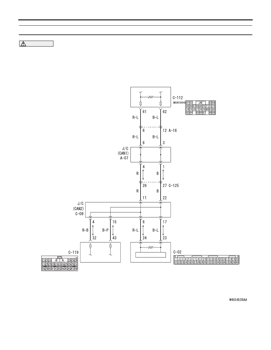
Diagnostic Item 35: Diagnose the lines from the main bus line to the SRS-ECU <RH drive vehicles>

CAUTION

When servicing a CAN bus line, earth yourself by 
touching a metal object such as an unpainted 
water pipe. If you fail to do, a component 
connected to the CAN bus line may be broken.

TROUBLE JUDGMENT

If the MUT-III can not received signal from the 
SRS-ECU, CAN bus line connector(s) are broken or 
an open circuit has occurred.

COMMENTS ON TROUBLE SYMPTOM

The wiring harness wire or connectors may have 
loose, corroded, or damage terminals, or terminals 
pushed back in the connector, or the SRS-ECU may 
be defective.

ENGINE-ECU<M/T>
ENGINE·A/T-ECU<A/T>

COMBINATION
METER

SRS-
ECU

Wire colour code
B : Black     LG : Light green     G : Green     L : Blue     W : White     Y : Yellow     SB : Sky blue
BR : Brown     O : Orange     GR : Gray     R : Red     P : Pink     V : Violet

DIAGNOSIS

CONTROLLER AREA NETWORK (CAN)

54D-607

POSSIBLE CAUSES

• Damaged harness wires and connectors

• Malfunction of the SRS-ECU

DIAGNOSTIC PROCEDURE

STEP 1. Connector check: C-09 joint connector 
(CAN2) connector and C-119 SRS-ECU connector

CAUTION

The strand end of the twist wire should be within 
10 cm from the connector. For details refer to 

P.54D-8

.

When checking the joint connector, ensure that its 
wiring harness side and its short pins are not 
damaged.

Q: Are the check result normal?

YES : 

Go to Step 2 .

NO : 

Repair a defective connector or replace the 
joint connector.

STEP 2. Resistance measurement at C-09 joint 
connector (CAN2) and C-119 SRS-ECU 
connector.

CAUTION

A digital multimeter should be used. For details 
refer to 

P.54D-8

.

CAUTION

The test wiring harness should be used. For 
details refer to 

P.54D-8

.

(1) Disconnect the joint connector (CAN2) and the 

SRS-ECU connector, and measure at the wiring 
harness side.

(2) Ignition switch: OFF (LOCK)

CAUTION

When measuring the resistance, disconnect the 
negative battery terminal. For details refer to 

P.54D-8

.

(3) Ensure that the negative battery terminal is 

AC310628AY

Connector: C-09 <RHD>

C-09 (GR)

Harness side

AC310631AZ

Connector: C-119 <RHD>

Harness side

C-119 (Y)

48

37

26

42

31

45

34

47

36

46

35

44

33

43

32

25 24

39

28

41

30

40

29

38

27

23

21

22

A

B

AC209350

1

12

2

13

3

14

4

15

5

16

6

17

7

18

8

19

9

20

10

21

11

22

AB

Short pin

AC310628AY

Connector: C-09 <RHD>

C-09 (GR)

Harness side

AC310631AZ

Connector: C-119 <RHD>

Harness side

C-119 (Y)

48

37

26

42

31

45

34

47

36

46

35

44

33

43

32

25 24

39

28

41

30

40

29

38

27

23

21

22

A

B

DIAGNOSIS

CONTROLLER AREA NETWORK (CAN)

54D-608

disconnected.

(4) Continuity between C-09 joint connector (CAN2) 

terminal No.4 and C-119 SRS-ECU connector 

terminal No.32

OK: 2 ohms or less

(5) Continuity between C-09 joint connector (CAN2) 

terminal No.15 and C-119 SRS-ECU connector 
terminal No.43

OK: 2 ohms or less

CAUTION

Strictly observe the specified wiring harness 
repair procedure. For details refer to 

P.54D-8

.

Q: Are the check result normal?

YES : 

<All the resistances measure 2 

Ω or less> 

Power supply to the SRS-ECU may be 
suspected. Diagnose the SRS system. 
Refer to 

P.52B-201

.

NO : 

<Either or all of the voltages measure more 
than 2 

Ω> Repair the wiring harness 

between the joint connector (CAN2) and the 
SRS-ECU connector.

AC312553

Harness side: C-09

Test
harness

Harness side: C-119

Test
harness

BP

AC312553 BQ

Test
harness

Harness side: C-09

Test
harness

Harness side: C-119

DIAGNOSIS

CONTROLLER AREA NETWORK (CAN)

54D-609

Diagnostic Item 36: Diagnose the lines from the main bus line to the steering wheel angle sensor <LH 
drive vehicles>

CAUTION

When servicing a CAN bus line, earth yourself by 
touching a metal object such as an unpainted 
water pipe. If you fail to do, a component 
connected to the CAN bus line may be broken.

ENGINE-ECU<M/T>
ENGINE·A/T-ECU<A/T>

COMBINATION
METER

STEERING
WHEEL
ANGLE
SENSOR

Wire colour code
B : Black     LG : Light green     G : Green     L : Blue     W : White     Y : Yellow     SB : Sky blue
BR : Brown     O : Orange     GR : Gray     R : Red     P : Pink     V : Violet


Content   ..  625  626  627  628   ..