Mitsubishi Grandis. Manual - part 600
 

  Index      Mitsubishi     Mitsubishi Grandis - service repair manual


Search            


Content   ..  598  599  600  601   ..


Mitsubishi Grandis. Manual - part 600


DIAGNOSIS

CONTROLLER AREA NETWORK (CAN)

54D-498

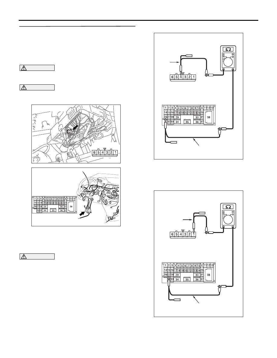
STEP 35. Resistance measurement at C-125 
intermediate connector and A-07 joint connector 
(CAN1).
NOTE: When checking A-07 joint connector (CAN1), 
disassemble and check the engine compartment 
relay box by referring to 

P.54D-616

.

CAUTION

A digital multimeter should be used. For details 
refer to 

P.54D-8

.

CAUTION

The test wiring harness should be used. For 
details refer to 

P.54D-8

.

(1) Disconnect the joint connector (CAN1) and the 

intermediate connector, and measure at the 
wiring harness side.

(2) Ignition switch: OFF (LOCK)

CAUTION

When measuring the resistance, disconnect the 
negative battery terminal. For details refer to 

P.54D-8

.

(3) Ensure that the negative battery terminal is 

disconnected.

(4) Continuity between C-125 intermediate 

connector terminal No.26 and A-07 joint 
connector (CAN1) terminal No.4

OK: 2 

 or less

(5) Continuity between C-125 intermediate 

connector terminal No.27 and A-07 joint 

AC302572AD

Connector: A-07

Harness side

AC310613

AD

Connector: C-125 <LHD>

AC312553 AU

Male side: C-125

Test harness

Harness side: A-07

Test
harness

AC312553

Male side: C-125

Test harness

 AV

Harness side: A-07

Test
harness

DIAGNOSIS

CONTROLLER AREA NETWORK (CAN)

54D-499

connector (CAN1) terminal No.1

OK: 2 

 or less

CAUTION

Strictly observe the specified wiring harness 
repair procedure. For details refer to 

P.54D-8

.

Q: Are the check results normal?

YES : 

<All the voltages measure 2 

Ω or less> Go 

to Step 36     .

NO : 

<Either or all of the resistances measure 
more than 2 

Ω> Repair the wiring harness 

between joint connector (CAN1) and the 
intermediate connector.

STEP 36. Resistance measurement at C-125 
intermediate connector and C-09 joint connector 
(CAN2).

CAUTION

A digital multimeter should be used. For details 
refer to 

P.54D-8

.

CAUTION

The test wiring harness should be used. For 
details refer to 

P.54D-8

.

(1) Disconnect the joint connector (CAN2) and the 

intermediate connector, and measure at the 
wiring harness side.

(2) Ignition switch: OFF (LOCK)

CAUTION

When measuring the resistance, disconnect the 
negative battery terminal. For details refer to 

P.54D-8

.

(3) Ensure that the negative battery terminal is 

disconnected.

(4) Continuity between C-125 intermediate 

connector terminal No.26 and C-09 joint 

AC310615

AU

Harness side

Connector: C-09 <LHD>

C-09 (GR)

AC310613

AD

Connector: C-125 <LHD>

AC312553

AC312553 AN

Harness side: C-09

Test
harness

Female side: C-125

Test harness

DIAGNOSIS

CONTROLLER AREA NETWORK (CAN)

54D-500

connector (CAN2) terminal No.11

OK: 2 

 or less

(5) Continuity between C-125 intermediate 

connector terminal No.27 and C-09 joint 
connector (CAN2) terminal No.22

OK: 2 

 or less

CAUTION

Strictly observe the specified wiring harness 
repair procedure. For details refer to 

P.54D-8

.

Q: Are the check results normal?

YES : 

<All the voltages measure 2 

Ω or less> Go 

to Step 37     .

NO : 

<Either or all of the resistances measure 
more than 2 

Ω> Repair the wiring harness 

between joint connector (CAN2) and the 
intermediate connector.

STEP 37. Resistance measurement at C-09 joint 
connector (CAN2) and C-126 diagnosis 
connector.

CAUTION

A digital multimeter should be used. For details 
refer to 

P.54D-8

.

CAUTION

The test wiring harness should be used. For 
details refer to 

P.54D-8

.

(1) Disconnect the connector, and measure at the 

wiring harness side.

(2) Ignition switch: OFF (LOCK)

CAUTION

When measuring the resistance, disconnect the 
negative battery terminal. For details refer to 

P.54D-8

.

(3) Ensure that the negative battery terminal is 

AC312553

AC312553 AP

Harness side: C-09

Test
harness

Female side: C-125

Test harness

AC310615

AU

Harness side

Connector: C-09 <LHD>

C-09 (GR)

AC310613

AO

Connector: C-126 <LHD>

Harness side 
(Front side)

C-126 (B)

DIAGNOSIS

CONTROLLER AREA NETWORK (CAN)

54D-501

disconnected.

(4) Continuity between C-09 joint connector (CAN2) 

terminal No.7 and C-126 diagnosis connector 

terminal No.6

OK: 2 

 or less

(5) Continuity between C-09 joint connector (CAN2) 

terminal No.18 and C-126 diagnosis connector 
terminal No.14

OK: 2 

 or less

CAUTION

Strictly observe the specified wiring harness 
repair procedure. For details refer to 

P.54D-8

.

Q: Are the check results normal?

YES : 

<All the resistances measure 2 

Ω or less> 

Diagnostics item 10: Diagnose shorts 
between CAN_L and H lines. Refer to 

P.54D-328

.

NO : 

<Either or all of the resistances measure 
more than 2 

Ω> Repair the wiring harness 

between joint connector (CAN1) and the 
diagnosis connector.

AC312553

Harness side: C-09

Test
harness

AX

Front side : C-126

Test
harness

AC312553 AZ

Front side : C-126

Test
harness

Test
harness

Harness side: C-09


Content   ..  598  599  600  601   ..