Mitsubishi Grandis. Manual - part 598
DIAGNOSIS
CONTROLLER AREA NETWORK (CAN)
54D-490
terminal No.43
OK: 2
Ω or less
CAUTION
Strictly observe the specified wiring harness
repair procedure. For details refer to
Q: Are the check results normal?
YES :
<All the resistances measure 2
Ω or less>
Power supply to the SRS-ECU may be
suspected. Diagnose the SRS system.
Refer to
NO :
<Either or all of the resistances measure
more than 2
Ω> Repair the wiring harness
between the joint connector (CAN2) and the
SRS-ECU connector.
STEP 22. Connector check: C-306 steering wheel
angle sensor connector
CAUTION
The strand end of the twist wire should be within
10 cm from the connector. For details refer to
Q: Is the check result normal?
YES :
Go to Step 23 .
NO :
Repair the defective connector.
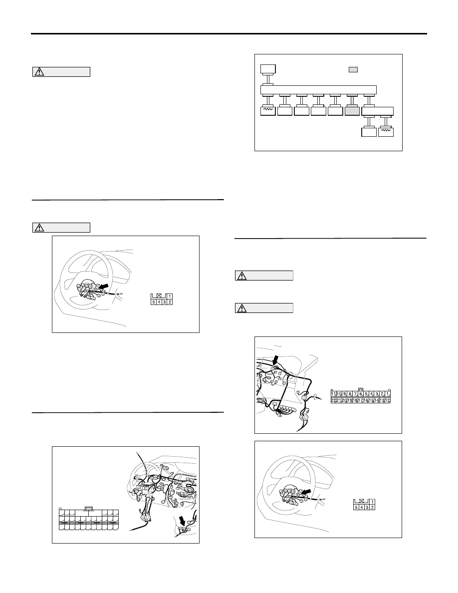
STEP 23. MUT-III CAN bus diagnostics (C-119
steering wheel angle sensor connector
disconnected)
(1) Disconnect the steering wheel angle sensor
connector, and diagnose by using the MUT-III.
(2) Check that the MUT-III indications correspond to
the illustration.
Q: Is the check result normal?
YES :
<MUT-III indications correspond to the
illustration> Go to Step 24 .
NO :
<MUT-III indications do not correspond to
the illustration> Go to Step 34 .
STEP 24. Resistance measurement at C-09 joint
connector (CAN2) and C-306 steering wheel
angle sensor connector.
CAUTION
A digital multimeter should be used. For details
refer to
.
CAUTION
The test wiring harness should be used. For
details refer to
(1) Disconnect the joint connector (CAN2) and the
steering wheel angle sensor connector, and
measure at the wiring harness side.
AC310153AF
Connector: C-306 <LHD>
Harness side
AC310613
BD
Connector: C-119
<LHD>
Harness side
C-119 (Y)
48
37
26
42
31
45
34
47
36
46
35
44
33
43
32
25 24
39
28
41
30
40
29
38
27
23
21
22
A
B
AC309834
MUT
J/C (2)
METER
ETAC S
J/C (1)
ASC -ECU
ENG/AT-ECU
A/C -ECU
SRS-ECU
STR. A .
SNSR
C. DISPL AY
AN
: Red section
on screen
AC310615
AU
Harness side
Connector: C-09 <LHD>
C-09 (GR)
AC310153AF
Connector: C-306 <LHD>
Harness side