Mitsubishi Grandis. Manual - part 583


  Index      Mitsubishi     Mitsubishi Grandis - service repair manual


Search            


Content   ..  581  582  583  584   ..


Mitsubishi Grandis. Manual - part 583


DIAGNOSIS

CONTROLLER AREA NETWORK (CAN)

54D-430

No.61.

OK: 2 

 or less

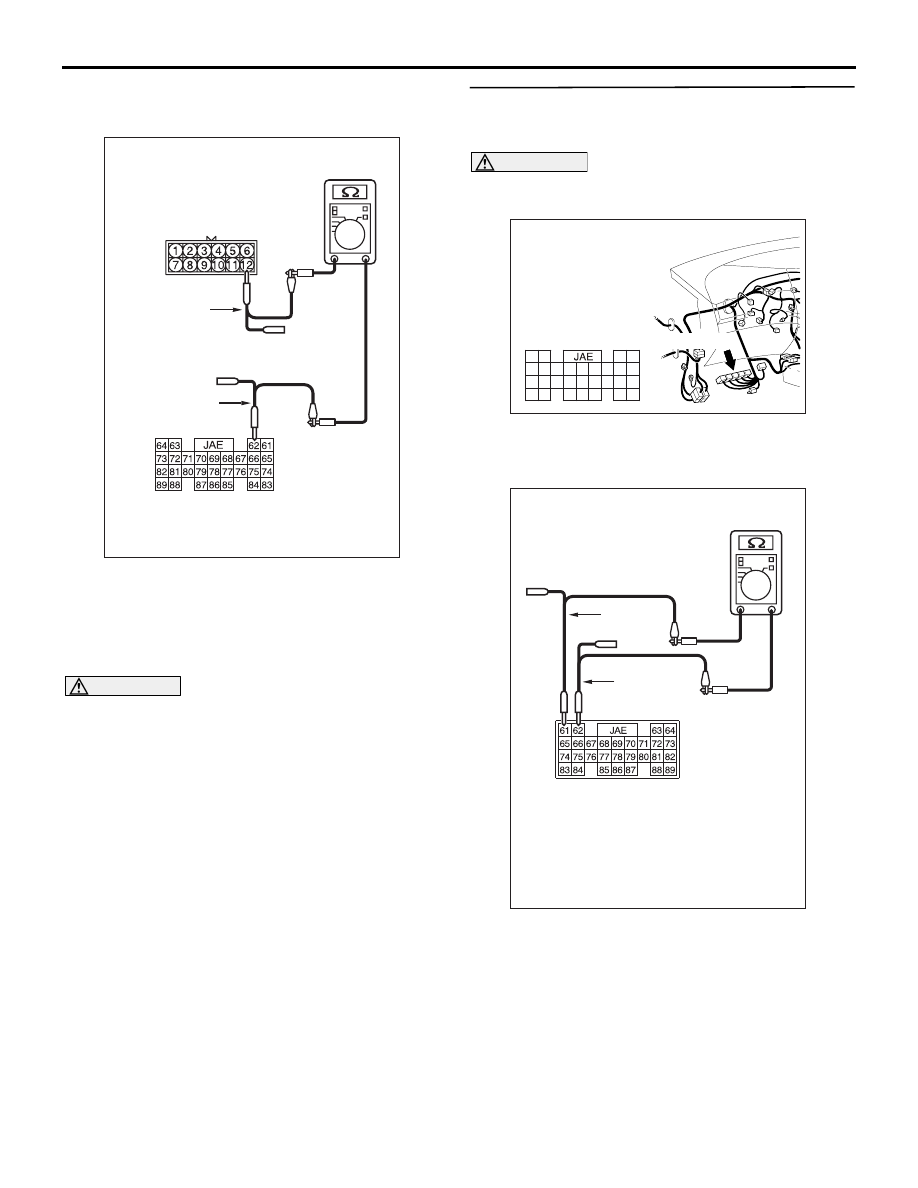
(5) Continuity between A-16 intermediate connector 

terminal No.12 and C-112 engine-ECU <M/T> or 
engine-A/T-ECU <A/T> connector terminal 
No.62.

OK: 2 

 or less

CAUTION

Strictly observe the specified wiring harness 
repair procedure. For details refer to 

P.54D-8

.

Q: Are the check result normal?

YES : 

<All the voltages measure 2 

Ω or less> Go 

to Step 14   .

NO : 

<Either or all of the voltages measure more 
than 2 

Ω> Repair the wiring harness 

between the engine-ECU <M/T> or 
engine-A/T-ECU <A/T> connector and the 
intermediate connector, and then go to Step 
8.

STEP 14. Resistance measurement at C-112 
engine-ECU <M/T> or engine-A/T-ECU <A/T> 
connector.

CAUTION

A digital multimeter should be used. For details 
refer to 

P.54D-8

.

(1) Remove the engine-ECU <M/T> or 

engine-A/T-ECU <A/T>, and measure at the 
equipment side.

(2) Resistance at C-112 engine-ECU <M/T> or 

engine-A/T-ECU <A/T> connector terminal Nos. 
61 and 62

OK: 120

± 20 

Q: Is the check result normal?

YES : 

<Within 120

± 20 Ω> Go to Step 8 .

NO : 

<Not within 120

± 20 Ω> Replace the 

engine-ECU <M/T> or engine-A/T-ECU 
<A/T>, and then go to Step 8.

AC312553

Harness side: C-112

Test
harness

AT

Test
harness

Male side: A-16

AC310628AW

Harness side

Connector: C-112 <RHD>

C-112 (GR)

61

62

63

64

65

66

67

68

69

70

71

72

73

74

75

76

77

78

79

80

81

82

83

84

85

86

87

88

89

AC312553

Equipment side: C-112

Test
harness

AC

Test
harness

DIAGNOSIS

CONTROLLER AREA NETWORK (CAN)

54D-431

STEP 15. Resistance measurement at C-125 
intermediate connector and A-07 joint connector 
(CAN1).
NOTE: When checking A-07 joint connector (CAN1), 
disassemble and check the engine compartment 
relay box by referring to 

P.54D-616

.

CAUTION

A digital multimeter should be used. For details 
refer to 

P.54D-8

.

CAUTION

The test wiring harness should be used. For 
details refer to 

P.54D-8

.

(1) Disconnect the joint connector (CAN1) and the 

intermediate connector, and measure at the 
wiring harness side.

(2) Ignition switch: OFF (LOCK)

CAUTION

When measuring the resistance, disconnect the 
negative battery terminal. For details refer to 

P.54D-8

.

(3) Ensure that the negative battery terminal is 

disconnected.

(4) Continuity between C-125 intermediate 

connector terminal No.26 and A-07 joint 
connector (CAN1) terminal No.4

OK: 2 

 or less

(5) Continuity between C-125 intermediate 

connector terminal No.27 and A-07 joint 

AC302572AD

Connector: A-07

Harness side

AC310628AB

Connector: C-125 <RHD>

AC312553 AU

Male side: C-125

Test harness

Harness side: A-07

Test
harness

AC312553

Male side: C-125

Test harness

 AV

Harness side: A-07

Test
harness

DIAGNOSIS

CONTROLLER AREA NETWORK (CAN)

54D-432

connector (CAN1) terminal No.1

OK: 2 

 or less

CAUTION

Strictly observe the specified wiring harness 
repair procedure. For details refer to 

P.54D-8

.

Q: Are the check result normal?

YES : 

<All the voltages measure 2 

Ω or less> Go 

to Step 8   .

NO : 

<Either or all of the voltages measure more 
than 2 

Ω> Repair the wiring harness 

between joint connector (CAN1) and the 
intermediate connector, and then go to Step 
8.

STEP 16. Connector check: C-126 diagnosis 
connector

CAUTION

The strand end of the twist wire should be within 
10 cm from the connector. For details refer to 

P.54D-8

.

Q: Is the check result normal?

YES : 

Go to Step 17.

NO : 

Repair the connector, or replace the joint 
connector. Then go to Step 17.

STEP 17. Resistance measurement at C-09 joint 
connector (CAN2) and C-126 diagnosis 
connector.

CAUTION

A digital multimeter should be used. For details 
refer to 

P.54D-8

.

CAUTION

The test wiring harness should be used. For 
details refer to 

P.54D-8

.

(1) Disconnect the joint connector (CAN2) and the 

diagnosis connector, and measure at the wiring 
harness side.

(2) Ignition switch: OFF (LOCK)

CAUTION

When measuring the resistance, disconnect the 
negative battery terminal. For details refer to 

P.54D-8

.

(3) Ensure that the negative battery terminal is 

AC310631AK

Connector: C-126 <RHD>

C-126 (B)

Harness side 
(Front side)

AC310628AY

Connector: C-09 <RHD>

C-09 (GR)

Harness side

AC310631AK

Connector: C-126 <RHD>

C-126 (B)

Harness side 
(Front side)

DIAGNOSIS

CONTROLLER AREA NETWORK (CAN)

54D-433

disconnected.

(4) Continuity between C-09 joint connector (CAN2) 

terminal No.7 and C-126 diagnosis connector 

terminal No.6

OK: 2 

 or less

(5) Continuity between C-09 joint connector (CAN2) 

terminal No.18 and C-126 diagnosis connector 
terminal No.14

OK: 2 

 or less

CAUTION

Strictly observe the specified wiring harness 
repair procedure. For details refer to 

P.54D-8

.

Q: Are the check result normal?

YES <all the resistances measure 2 

 or less: 

When any repair done> : 

Retest the system.

YES <all the resistances measure 2 

 or less: 

When no repair done> : 

Diagnose CAN bus lines 

thoroughly 

P.54D-16

. Refer to .

<Either of the resistances measures more than 2 


or all the resistances measure more than 2 

> : 

Repair the wiring harness between joint 
connector (CAN2) and the diagnosis 
connector.

AC312553

Harness side: C-09

Test
harness

AX

Front side : C-126

Test
harness

AC312553 AZ

Front side : C-126

Test
harness

Test
harness

Harness side: C-09


Content   ..  581  582  583  584   ..