Mitsubishi Grandis. Manual - part 581


  Index      Mitsubishi     Mitsubishi Grandis - service repair manual


Search            


Content   ..  579  580  581  582   ..


Mitsubishi Grandis. Manual - part 581


DIAGNOSIS

CONTROLLER AREA NETWORK (CAN)

54D-422

terminal Nos. 6 and 17

OK: 120 

± 20 

Q: Is the check result normal?

YES : 

<Within 120 

± 20 Ω> Go to Step 7 .

NO : 

<Not within 120 

± 20 Ω> Go to Step 5 .

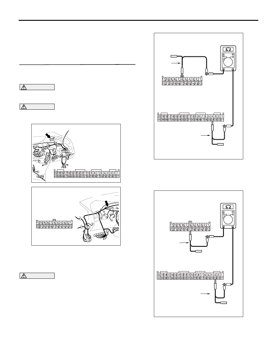
STEP 5. Resistance measurement at C-09 joint 
connector (CAN2) and C-02 combination meter 
connector.

CAUTION

A digital multimeter should be used. For details 
refer to 

P.54D-8

.

CAUTION

The test wiring harness should be used. For 
details refer to 

P.54D-8

.

(1) Disconnect the joint connector (CAN2) and the 

combination meter connector, and measure at 
the wiring harness side.

(2) Ignition switch: OFF (LOCK)

CAUTION

When measuring the resistance, disconnect the 
negative battery terminal. For details refer to 

P.54D-8

.

(3) Ensure that the negative battery terminal is 

disconnected.

(4) Continuity between C-09 joint connector (CAN2) 

terminal No.6 and C-02 combination meter 
connector terminal No.24

OK: 2 

 or less

(5) Continuity between C-09 joint connector (CAN2) 

terminal No.17 and C-02 combination meter 

AC310631AX

Connector: C-02 <RHD>

Harness side

C-02

AC310628AY

Connector: C-09 <RHD>

C-09 (GR)

Harness side

AC312553  AJ

Harness side: C-09

Test
harness

Harness side: C-02

Test
harness

AC312553  AL

Harness side: C-09

Harness side: C-02

Test
harness

Test
harness

DIAGNOSIS

CONTROLLER AREA NETWORK (CAN)

54D-423

connector terminal No.23

OK: 2 

 or less

CAUTION

Strictly observe the specified wiring harness 
repair procedure. For details refer to 

P.54D-8

.

Q: Are the check result normal?

YES : 

<All the voltages measure 2 

Ω or less> Go 

to Step 6 .

NO : 

<Either or all of the voltages measure more 
than 2 

Ω> Repair the wiring harness 

between joint connector (CAN2) and the 
combination meter connector, and then go 
to Step 2.

STEP 6. Resistance measurement at C-02 
combination meter connector.

CAUTION

A digital multimeter should be used. For details 
refer to 

P.54D-8

.

(1) Remove the combination meter, and measure at 

the equipment side.

(2) Resistance between C-02 combination meter 

connector terminal Nos. 23 and 24

OK: 120

± 20 

Q: Is the check result normal?

YES : 

<Within 120

± 20 Ω> Go to Step 2 .

NO : 

<Not within 120

± 20 Ω> Replace the 

combination meter, and then go to Step 2.

AC310631AX

Connector: C-02 <RHD>

Harness side

C-02

AC204740

AC204740

AC204740

AC204740DS

Equipment side: C-02

Test
harness

DIAGNOSIS

CONTROLLER AREA NETWORK (CAN)

54D-424

STEP 7. Resistance measurement at C-125 
intermediate connector and C-09 joint connector 
(CAN2).

CAUTION

A digital multimeter should be used. For details 
refer to 

P.54D-8

.

CAUTION

The test wiring harness should be used. For 
details refer to 

P.54D-8

.

(1)  Disconnect the joint connector (CAN2) and the 

intermediate connector, and measure at the 
wiring harness side.

(2) Ignition switch: OFF (LOCK)

CAUTION

When measuring the resistance, disconnect the 
negative battery terminal. For details refer to 

P.54D-8

.

(3) Ensure that the negative battery terminal is 

disconnected.

(4) Continuity between C-125 intermediate 

connector terminal No.26 and C-09 joint 
connector (CAN2) terminal No.11

OK: 2 

 or less

(5) Continuity between C-125 intermediate 

connector terminal No.27 and C-09 joint 

AC310628AY

Connector: C-09 <RHD>

C-09 (GR)

Harness side

AC310628AB

Connector: C-125 <RHD>

AC312553

AC312553 AN

Harness side: C-09

Test
harness

Female side: C-125

Test harness

AC312553

AC312553 AP

Harness side: C-09

Test
harness

Female side: C-125

Test harness

DIAGNOSIS

CONTROLLER AREA NETWORK (CAN)

54D-425

connector (CAN2) terminal No.22

OK: 2 

 or less

CAUTION

Strictly observe the specified wiring harness 
repair procedure. For details refer to 

P.54D-8

.

Q: Are the check result normal?

YES : 

<All the voltages measure 2 

Ω or less> Go 

to Step 2 .

NO : 

<Either or all of the voltages measure more 
than 2 

Ω> Repair the wiring harness 

between joint connector (CAN2) and the 
intermediate connector, and then go to Step 
2.

STEP 8. Resistance measurement at the C-125 
intermediate connector.

CAUTION

A digital multimeter should be used. For details 
refer to 

P.54D-8

.

CAUTION

The test wiring harness should be used. For 
details refer to 

P.54D-8

.

(1) Disconnect the connector, and measure at its 

male-side intermediate connector (at the front 
wiring harness side).

(2) Ignition switch: OFF (LOCK)

CAUTION

When measuring the resistance, disconnect the 
negative battery terminal. For details refer to 

P.54D-8

.

(3) Ensure that the negative battery terminal is 

disconnected.

(4) Resistance between C-125 intermediate 

connector terminal Nos.26 and 27

OK: 120

± 20 

Q: Is the check result normal?

YES : 

<Within 120

± 20 Ω> Go to Step 16 .

NO : 

<Not within 120

± 20 Ω> Go to Step 9 .

AC310628AB

Connector: C-125 <RHD>

AC204740

AC204740

AC204740

AC204740

AC204740DC

Male side: C-125

Test
harness


Content   ..  579  580  581  582   ..