Mitsubishi Grandis. Manual - part 580


  Index      Mitsubishi     Mitsubishi Grandis - service repair manual


Search            


Content   ..  578  579  580  581   ..


Mitsubishi Grandis. Manual - part 580


DIAGNOSIS

CONTROLLER AREA NETWORK (CAN)

54D-418

disconnected.

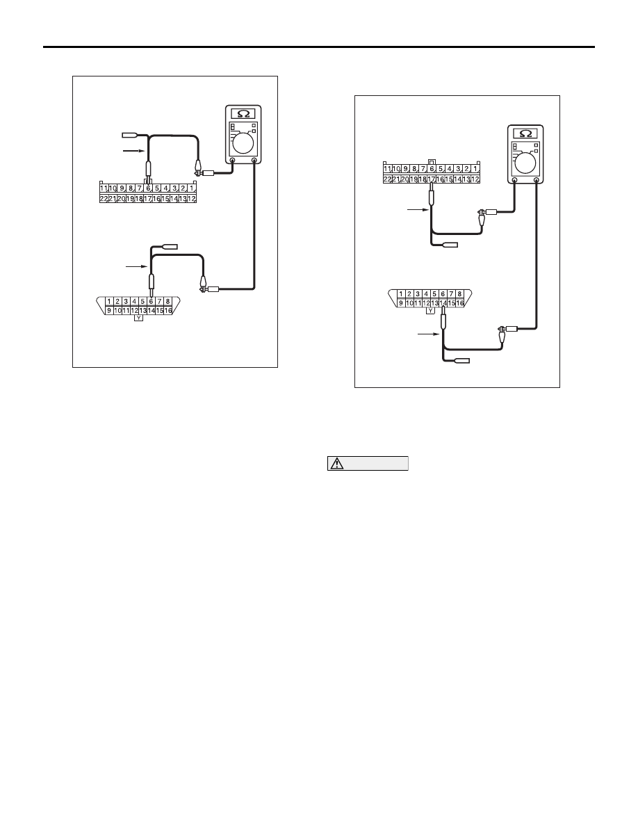
(4) Continuity between C-09 joint connector (CAN2) 

terminal No.6 and C-126 diagnosis connector 

terminal No.6

OK: 2 

 or less

(5) Continuity between C-09 joint connector (CAN2) 

terminal No.17 and C-126 diagnosis connector 
terminal No.14

OK: 2 

 or less

CAUTION

Strictly observe the specified wiring harness 
repair procedure. For details refer to 

P.54D-8

.

Q: Are the check result normal?

YES <all the resistances measure 2 

 or less: 

When any repair done> : 

Retest the system.

YES <all the resistances measure 2 

 or less: 

When no repair done> : 

Diagnose CAN bus lines 

thoroughly. Refer to 

P.54D-16

.

<Either of the resistances measures more than 2 


or all the resistances measure more than 2 

> : 

Repair the wiring harness between joint 
connector (CAN2) and the diagnosis 
connector.

AC312553 AW

Harness side: C-09

Test
harness

Front side : C-126

Test
harness

AC312553

Front side : C-126

Test
harness

Test
harness

Harness side: C-09

AY

DIAGNOSIS

CONTROLLER AREA NETWORK (CAN)

54D-419

Diagnostic Item 14: Diagnose the terminator resistors at both ends <RH drive vehicles>

CAUTION

When servicing a CAN bus line, earth yourself by 
touching a metal object such as an unpainted 
water pipe. If you fail to do, a component 
connected to the CAN bus line may be broken.

ENGINE-ECU<M/T>
ENGINE·A/T-ECU<A/T>

COMBINATION
METER

DIAGNOSIS
CONNECTOR

Wire colour code
B : Black     LG : Light green     G : Green     L : Blue     W : White     Y : Yellow     SB : Sky blue
BR : Brown     O : Orange     GR : Gray     R : Red     P : Pink     V : Violet

DIAGNOSIS

CONTROLLER AREA NETWORK (CAN)

54D-420

TROUBLE JUDGMENT

If the resistance between the CAN bus lines (CAN_L 
and CAN_H) is infinite, the terminator resistors in the 
CAN bus lines are broken, or there is an open circuit 
in the wiring harness from the diagnosis connector to 
the terminator resistors.

COMMENTS ON TROUBLE SYMPTOM

The CAN bus line harness wires or connectors may 
be damaged (open circuit may be present on CAN_L 
or CAN_H line between the diagnosis connector and 
CAN main bus lines, or CAN main bus lines may be 
open at both sides), or the combination meter and 
the engine-ECU <M/T> or engine-A/T-ECU <A/T> 
may be defective.

TROUBLESHOOTING HINTS

• Damaged harness wires and connectors

• Malfunction of the combination meter

• Malfunction of the engine-ECU <M/T> or 

engine-A/T-ECU <A/T>

DIAGNOSTIC PROCEDURE

STEP 1. Connector check: C-125 intermediate 
connector

CAUTION

The strand end of the twist wire should be within 
10 cm from the connector. For details refer to 

P.54D-8

.

Q: Is the check result normal?

YES : 

Go to Step 2 .

NO : 

Repair the connector, and then go to Step 2.

STEP 2. Resistance measurement at the C-125 
intermediate connector.

CAUTION

A digital multimeter should be used. For details 
refer to 

P.54D-8

.

CAUTION

The test wiring harness should be used. For 
details refer to 

P.54D-8

.

(1) Disconnect the connector, and measure at its 

female-side intermediate connector (at the 
instrument panel wiring harness side).

(2) Ignition switch: OFF (LOCK)

CAUTION

When measuring the resistance, disconnect the 
negative battery terminal. For details refer to 

P.54D-8

.

(3) Ensure that the negative battery terminal is 

disconnected.

(4) Resistance between C-125 intermediate 

AC310628AB

Connector: C-125 <RHD>

AC310628AB

Connector: C-125 <RHD>

AC204740

AC204740

AC204740

AC204740

AC204740DC

Male side: C-125

Test
harness

DIAGNOSIS

CONTROLLER AREA NETWORK (CAN)

54D-421

connector terminal Nos.26 and 27

OK: 120

± 20 

Q: Is the check result normal?

YES : 

<Within 120

± 20 Ω> Go to Step 8 .

NO : 

<Not within 120

± 20 Ω> Go to Step 3 .

STEP 3. Connector check: C-09 joint connector 
(CAN2) and C-02 combination meter connector

CAUTION

The strand end of the twist wire should be within 
10 cm from the connector. For details refer to 

P.54D-8

.

When checking the joint connector, ensure that its 
wiring harness side is not damaged.

Q: Are the check result normal?

YES : 

Go to Step 4.

NO : 

Repair the connector, or replace the joint 
connector. Then go to Step 2.

STEP 4. Resistance measurement at C-09 joint 
connector (CAN2).

CAUTION

A digital multimeter should be used. For details 
refer to 

P.54D-8

.

CAUTION

The test wiring harness should be used. For 
details refer to 

P.54D-8

.

(1) Disconnect the connector, and measure at the 

wiring harness side.

(2) Ignition switch: OFF (LOCK)

CAUTION

When measuring the resistance, disconnect the 
negative battery terminal. For details refer to 

P.54D-8

.

(3) Ensure that the negative battery terminal is 

disconnected.

(4) Resistance between C-09 joint connector (CAN2) 

AC310631AX

Connector: C-02 <RHD>

Harness side

C-02

AC310628AY

Connector: C-09 <RHD>

C-09 (GR)

Harness side

AC209350

1

12

2

13

3

14

4

15

5

16

6

17

7

18

8

19

9

20

10

21

11

22

AC

Short pin

AC310628AY

Connector: C-09 <RHD>

C-09 (GR)

Harness side

AC204740DI

Harness side: C-09

Test
harness

Test
harness


Content   ..  578  579  580  581   ..