Mitsubishi Grandis. Manual - part 576


  Index      Mitsubishi     Mitsubishi Grandis - service repair manual


Search            


Content   ..  574  575  576  577   ..


Mitsubishi Grandis. Manual - part 576


DIAGNOSIS

CONTROLLER AREA NETWORK (CAN)

54D-402

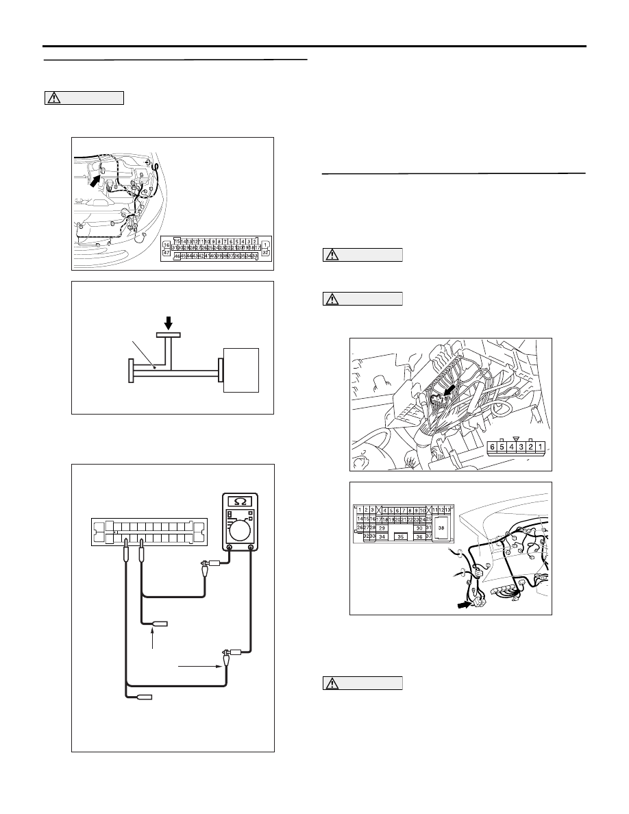
STEP 39. Resistance measurement at A-04 
ASC-ECU connector.

CAUTION

A digital multimeter should be used. For details 
refer to 

P.54D-8

.

(1) Connect special tool MB991974 to the ASC-ECU 

connector, and measure by using the check 
connector (connect the ECU side only).

(2) Resistance between special tool MB991974 

check connector terminal Nos. 11 and 15.

OK: 1 k

 or more

Q: Is the check result normal?

YES : 

<1 k

Ω or more> Follow diagnostic item 20, 

Diagnose CAN bus lines thoroughly. Refer 
to 

P.54D-526

.

NO : 

<Less than 1 k

Ω> Replace the ASC-ECU.

STEP 40. Resistance measurement at the A-07 
joint connector (CAN1).
NOTE: When checking A-07 joint connector (CAN1), 
disassemble and check the engine compartment 
relay box by referring to 

P.54D-616

.

CAUTION

A digital multimeter should be used. For details 
refer to 

P.54D-8

.

CAUTION

The test wiring harness should be used. For 
details refer to 

P.54D-8

.

(1) Disconnect the joint connector (CAN1) and the 

intermediate connector, and measure at the 
wiring harness side.

(2) Ignition switch: OFF (LOCK)

CAUTION

When measuring the resistance, disconnect the 
negative battery terminal. For details refer to 

P.54D-8

.

(3) Ensure that the negative battery terminal is 

AC310398

AJ

Connector: A-04 <RHD>

A-04

Harness side

AC304012

MB991984

Check connector

AC

ASC-ECU

AC204740

1

3

4

5

6

7

8

9

10

11

2

13 12

16

17

18

19

20

21

22

23

24

15

25

14

26

AC204740

AC204740

AC204740

AC204740BD

Special tool MB991974: 
Check connector

Check 
harness

AC302572AD

Connector: A-07

Harness side

AC310628AB

Connector: C-125 <RHD>

DIAGNOSIS

CONTROLLER AREA NETWORK (CAN)

54D-403

disconnected.

(4) Measure the continuity between A-07 joint 

connector (CAN1) terminal Nos. 1 and 4.

OK: More than 2 

CAUTION

Strictly observe the specified wiring harness 
repair procedure. For details refer to 

P.54D-8

.

Q: Is the check result normal?

YES : 

<2 more than 

Ω> Follow diagnostic item 20, 

Diagnose CAN bus lines thoroughly. Refer 
to 

P.54D-526

.

NO : 

<2 

Ω or less> Repair the wiring harness 

between joint connector (CAN1) and the 
intermediate connector.

AC204740

AC204740

AC204740

AC204740

AC204740

AC204740

AC204740DN

Harness side: A-07

Test
harness

Test
harness

DIAGNOSIS

CONTROLLER AREA NETWORK (CAN)

54D-404

Diagnostic Item 13: Diagnose the terminator resistors at both ends <LH drive vehicles>

CAUTION

When servicing a CAN bus line, earth yourself by 
touching a metal object such as an unpainted 
water pipe. If you fail to do, a component 
connected to the CAN bus line may be broken.

ENGINE-ECU<M/T>
ENGINE·A/T-ECU<A/T>

COMBINATION
METER

DIAGNOSIS
CONNECTOR

Wire colour code
B : Black     LG : Light green     G : Green     L : Blue     W : White     Y : Yellow     SB : Sky blue
BR : Brown     O : Orange     GR : Gray     R : Red     P : Pink     V : Violet

DIAGNOSIS

CONTROLLER AREA NETWORK (CAN)

54D-405

TROUBLE JUDGMENT

If the resistance between the CAN bus lines (CAN_L 
and CAN_H) is infinite, the terminator resistors in the 
CAN bus lines are broken, or there is an open circuit 
in the wiring harness from the diagnosis connector to 
the terminator resistors.

COMMENTS ON TROUBLE SYMPTOM

The CAN bus line harness wires or connectors may 
be damaged (open circuit may be present on CAN_L 
or CAN_H line between the diagnosis connector and 
CAN main bus lines, or CAN main bus lines may be 
open at both sides), or the combination meter and 
the engine-ECU <M/T> or engine-A/T-ECU <A/T> 
may be defective.

TROUBLESHOOTING HINTS

• Damaged harness wires and connectors

• Malfunction of the combination meter

• Malfunction of the engine-ECU <M/T> or 

engine-A/T-ECU <A/T>

DIAGNOSTIC PROCEDURE

STEP 1. Connector check: C-125 intermediate 
connector

CAUTION

The strand end of the twist wire should be within 
10 cm from the connector. For details refer to 

P.54D-8

.

Q: Is the check result normal?

YES : 

Go to Step 2 .

NO : 

Repair the connector, and then go to Step 2.

STEP 2. Resistance measurement at the C-125 
intermediate connector.

CAUTION

A digital multimeter should be used. For details 
refer to 

P.54D-8

.

CAUTION

The test wiring harness should be used. For 
details refer to 

P.54D-8

.

(1) Disconnect the connector, and measure at its 

female-side intermediate connector (at the 
instrument panel wiring harness side).

(2) Ignition switch: OFF (LOCK)

CAUTION

When measuring the resistance, disconnect the 
negative battery terminal. For details refer to 

P.54D-8

.

(3) Ensure that the negative battery terminal is 

disconnected.

(4) Resistance between C-125 intermediate 

AC310613

AD

Connector: C-125 <LHD>

AC310613

AD

Connector: C-125 <LHD>

AC204740

AC204740

AC204740

AC204740

AC204740DC

Male side: C-125

Test
harness


Content   ..  574  575  576  577   ..