Mitsubishi Grandis. Manual - part 560


  Index      Mitsubishi     Mitsubishi Grandis - service repair manual


Search            


Content   ..  558  559  560  561   ..


Mitsubishi Grandis. Manual - part 560


DIAGNOSIS

CONTROLLER AREA NETWORK (CAN)

54D-338

STEP 14. Connector check: C-37 jumper 
connector

CAUTION

The strand end of the twist wire should be within 
10 cm from the connector. For details refer to 

P.54D-8

.

Check that the wiring harness of the jumper 
connector is not damaged.

Q: Is the check result normal?

YES : 

Go to Step 15.

NO : 

Repair the defective connector.

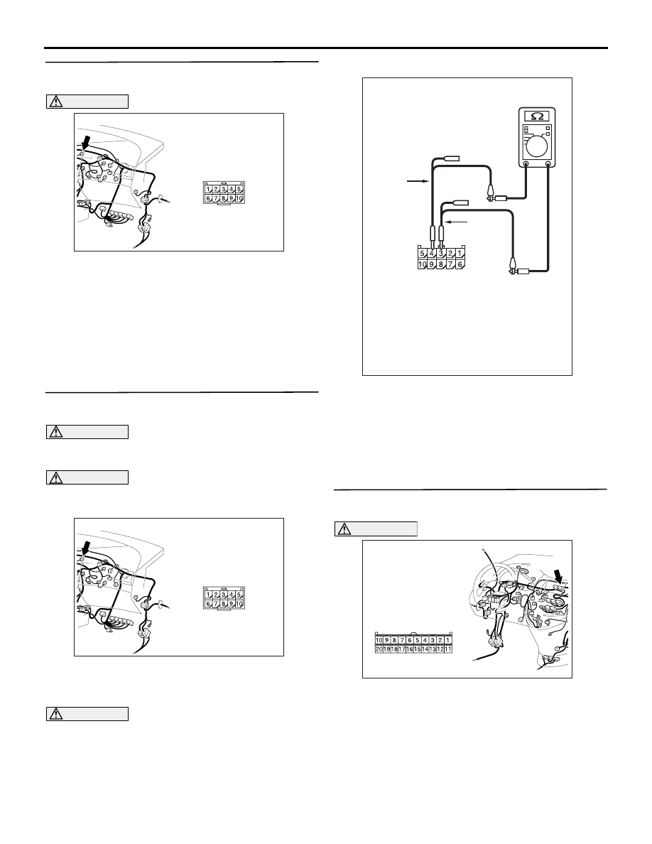
STEP 15. Resistance measurement at the C-37 
jumper connector.

CAUTION

A digital multimeter should be used. For details 
refer to 

P.54D-8

.

CAUTION

The test wiring harness should be used. For 
details refer to 

P.54D-8

.

(1) Disconnect the connector, and measure at its 

jumper connector (at the centre display side).

(2) Ignition switch: OFF (LOCK)

CAUTION

When measuring the resistance, disconnect the 
negative battery terminal. For details refer to 

P.54D-8

.

(3) Ensure that the negative battery terminal is 

disconnected.

(4) Resistance between C-37 jumper connector 

terminal Nos. 3 and 4

OK: 1 k

 or more

Q: Is the check result normal?

YES : 

<1 k

Ω or more> Go to Step 19 .

NO : 

<Less than 1 k

Ω> Go to Step 16 .

STEP 16. Connector check: C-07 centre display 
connector

CAUTION

The strand end of the twist wire should be within 
10 cm from the connector. For details refer to 

P.54D-8

.

Q: Is the check result normal?

YES : 

Go to Step 17 .

NO : 

Repair the defective connector.

AC310615

AV

Connector: C-37 <LHD>

AC310615

AV

Connector: C-37 <LHD>

AC312553 AF

Harness side: C-37

Test 
harness

Test 
harness

AC310613

BC

Connector: C-07 <LHD>

Harness side

C-07 (B)

DIAGNOSIS

CONTROLLER AREA NETWORK (CAN)

54D-339

STEP 17. Resistance measurement at the C-37 
jumper connector.

CAUTION

A digital multimeter should be used. For details 
refer to 

P.54D-8

.

CAUTION

The test wiring harness should be used. For 
details refer to 

P.54D-8

.

(1) Disconnect the centre display connector and the 

jumper connector, and measure at the jumper 
connector (at the centre display side).

(2) Ignition switch: OFF (LOCK)

CAUTION

When measuring the resistance, disconnect the 
negative battery terminal. For details refer to 

P.54D-8

.

(3) Ensure that the negative battery terminal is 

disconnected.

(4) Resistance between C-37 jumper connector 

terminal Nos. 3 and 4

OK: More than 2 

CAUTION

Strictly observe the specified wiring harness 
repair procedure. For details refer to 

P.54D-8

.

Q: Is the check result normal?

YES : 

<More than 2 

Ω> Go to Step 18.

NO : 

<2 

Ω or less> Repair the wiring harness 

between the jumper connector and the 
centre display connector.

STEP 18. Resistance measurement at C-07 centre 
display connector.

CAUTION

A digital multimeter should be used. For details 
refer to 

P.54D-8

.

(1) Remove the centre display connector, and 

AC310613

BC

Connector: C-07 <LHD>

Harness side

C-07 (B)

AC310615

AV

Connector: C-37 <LHD>

AC312553 AF

Harness side: C-37

Test 
harness

Test 
harness

AC310613

BC

Connector: C-07 <LHD>

Harness side

C-07 (B)

DIAGNOSIS

CONTROLLER AREA NETWORK (CAN)

54D-340

measure at the equipment side.

(2) Resistance at C-07 centre display connector 

terminal Nos. 5 and 15

OK: 1 k

 or more

Q: Is the check result normal?

YES : 

<1 k

Ω or more> Follow diagnostic item 18, 

Diagnose CAN bus lines thoroughly. Refer 
to 

P.54D-476

.

NO : 

<Less than 1 k

Ω> Replace the centre 

display connector.

STEP 19. Resistance measurement at the C-09 
joint connector (CAN2).

CAUTION

A digital multimeter should be used. For details 
refer to 

P.54D-8

.

CAUTION

The test wiring harness should be used. For 
details refer to 

P.54D-8

.

(1) Disconnect the connector, and measure at the 

wiring harness side.

(2) Ignition switch: OFF (LOCK)

CAUTION

When measuring the resistance, disconnect the 
negative battery terminal. For details refer to 

P.54D-8

.

(3) Ensure that the negative battery terminal is 

disconnected.

(4) Resistance between C-09 joint connector (CAN2) 

terminal Nos. 5 and 16

OK: 1 k

 or more

Q: Is the check result normal?

YES : 

<1 k

Ω or more> Follow diagnostic item 18 

"Diagnose CAN bus lines thoroughly." Refer 
to 

P.54D-476

.

NO : 

<Less than 1 k

Ω> Repair the wiring harness 

between the joint connector (CAN2) and the 
jumper connector.

AC312553

Test
harness

Equipment side: C-07

AG

Test
harness

AC310615

AU

Harness side

Connector: C-09 <LHD>

C-09 (GR)

AC204740DG

Harness side: C-09

Test
harness

Test
harness

DIAGNOSIS

CONTROLLER AREA NETWORK (CAN)

54D-341

STEP 20. Connector check: C-119 SRS-ECU 
connector

CAUTION

The strand end of the twist wire should be within 
10 cm from the connector. For details refer to 

P.54D-8

.

Q: Is the check result normal?

YES : 

Go to Step 21.

NO : 

Repair the defective connector.

STEP 21. Resistance measurement at C-09 joint 
connector (CAN2).

CAUTION

A digital multimeter should be used. For details 
refer to 

P.54D-8

.

CAUTION

The test wiring harness should be used. For 
details refer to 

P.54D-8

.

(1) Disconnect the joint connector (CAN2) and the 

SRS-ECU connector, and measure at the wiring 
harness side.

(2) Ignition switch: OFF (LOCK)

CAUTION

When measuring the resistance, disconnect the 
negative battery terminal. For details refer to 

P.54D-8

.

(3) Ensure that the negative battery terminal is 

disconnected.

(4) Continuity between C-09 joint connector (CAN2) 

terminal Nos. 1 and 12

OK: More than 2 

CAUTION

Strictly observe the specified wiring harness 
repair procedure. For details refer to 

P.54D-8

.

Q: Is the check result normal?

YES : 

<More than 2 

Ω> Go to Step 22.

NO : 

<2 

Ω or less> Repair the wiring harness 

between joint connector (CAN2) and the 
SRS-ECU connector.

AC310613

BD

Connector: C-119 
<LHD>

Harness side

C-119 (Y)

48

37

26

42

31

45

34

47

36

46

35

44

33

43

32

25 24

39

28

41

30

40

29

38

27

23

21

22

A

B

AC310615

AU

Harness side

Connector: C-09 <LHD>

C-09 (GR)

AC310613

BD

Connector: C-119 
<LHD>

Harness side

C-119 (Y)

48

37

26

42

31

45

34

47

36

46

35

44

33

43

32

25 24

39

28

41

30

40

29

38

27

23

21

22

A

B

AC204740DH

Harness side: C-09

Test
harness

Test
harness


Content   ..  558  559  560  561   ..