Mitsubishi Grandis. Manual - part 542
DIAGNOSIS
CONTROLLER AREA NETWORK (CAN)
54D-266
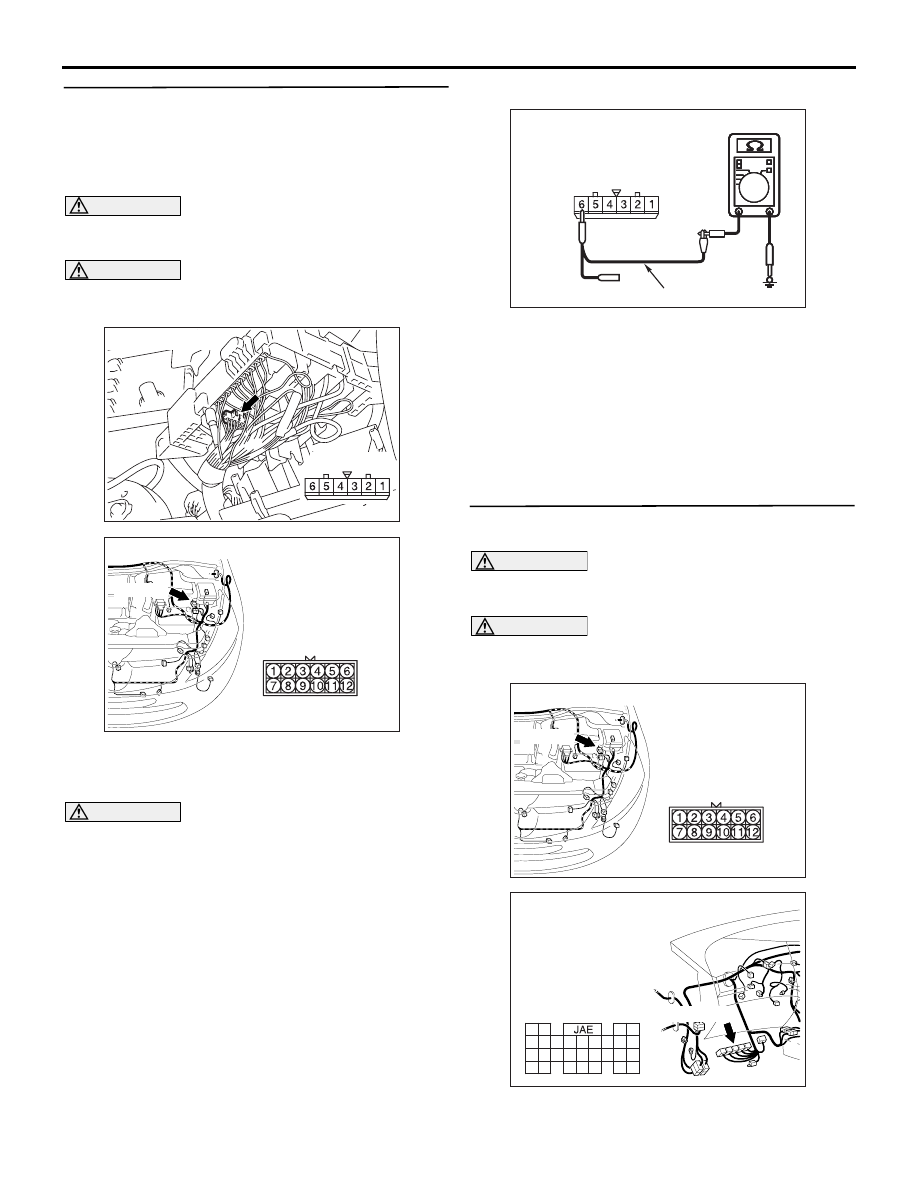
STEP 48. Resistance measurement at the A-07
joint connector (CAN1).
NOTE: When checking A-07 joint connector (CAN1),
disassemble and check the engine compartment
relay box by referring to
.
CAUTION
A digital multimeter should be used. For details
refer to
CAUTION
The test wiring harness should be used. For
details refer to
(1) Disconnect the joint connector (CAN1) and the
intermediate connector, and measure at the
wiring harness side.
CAUTION
When measuring the resistance, disconnect the
negative battery terminal. For details refer to
(2) Ensure that the negative battery terminal is
disconnected.
(3) Resistance between A-07 joint connector (CAN1)
terminal No.6 and body earth
OK: 1 k
Ω or more
Q: Is the check result normal?
YES :
<1 k
Ω or more> Go to Step 49.
NO :
<less than 1 k
Ω> Repair the wiring harness
between the joint connector (CAN1) and the
intermediate connector.
STEP 49. Resistance measurement at the A-16
intermediate connector.
CAUTION
A digital multimeter should be used. For details
refer to
.
CAUTION
The test wiring harness should be used. For
details refer to
(1) Disconnect the engine-ECU <M/T> or
engine-A/T-ECU <A/T> connector and the
AC302572AD
Connector: A-07
Harness side
AC310398
AC
Connector: A-16 <RHD>
A-16 (B)
AC209364
AC209364
AC209364
AC209364
Harness side: A-07
AC209364LZ
Test harness
AC310398
AC
Connector: A-16 <RHD>
A-16 (B)
AC310628AW
Harness side
Connector: C-112 <RHD>
C-112 (GR)
61
62
63
64
65
66
67
68
69
70
71
72
73
74
75
76
77
78
79
80
81
82
83
84
85
86
87
88
89