Mitsubishi Grandis. Manual - part 515


  Index      Mitsubishi     Mitsubishi Grandis - service repair manual


Search            


Content   ..  513  514  515  516   ..


Mitsubishi Grandis. Manual - part 515


DIAGNOSIS

CONTROLLER AREA NETWORK (CAN)

54D-158

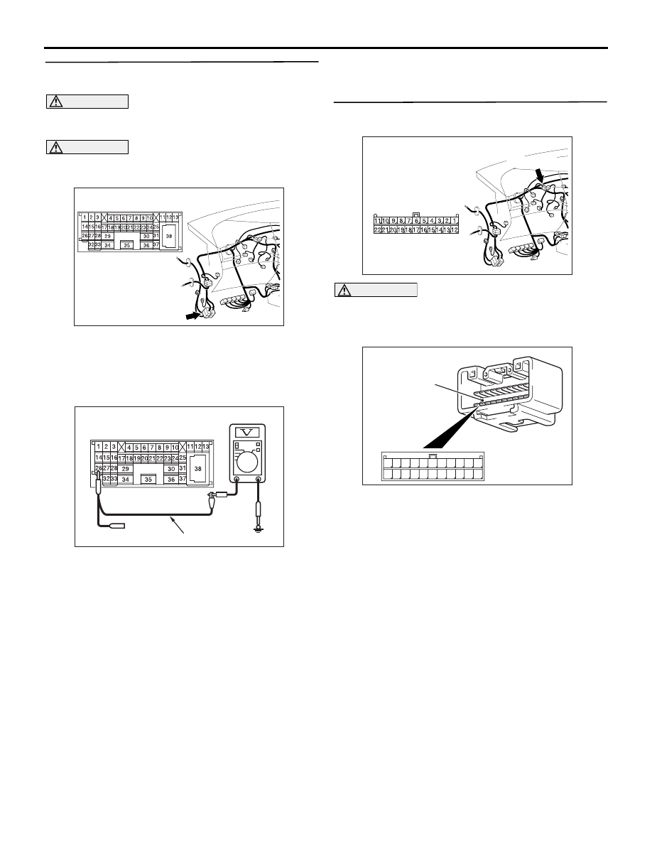
STEP 31. Voltage measurement at the C-125 
intermediate connector.

CAUTION

A digital multimeter should be used. For details 
refer to 

P.54D-8

.

CAUTION

The test wiring harness should be used. For 
details refer to 

P.54D-8

.

(1) Disconnect the connector, and measure at its 

male-side intermediate connector (at the front 
wiring harness side).

(2) Connect the negative battery terminal, and turn 

the ignition switch to the ON position.

(3) Voltage between C-125 intermediate connector 

terminal No.26 and body earth

OK: 4.0 V or less

Q: Is the check result normal?

YES : 

<4.0 V or less> Go to Step 32.

NO : 

<more than 4.0 V> Go to Step 49.

STEP 32. Connector check: C-09 joint connector 
(CAN2)

CAUTION

The strand end of the twist wire should be within 
10 cm from the connector. For details refer to 

P.54D-8

.

When checking the joint connector, ensure that its 
wiring harness side and its short pins are not 
damaged.

Q: Is the check result normal?

YES : 

Go to Step 33 .

NO : 

Repair a defective connector or replace the 
joint connector.

AC310628AB

Connector: C-125 <RHD>

AC209365KC

Male side: C-125

Test harness

AC310628AY

Connector: C-09 <RHD>

C-09 (GR)

Harness side

AC209350

1

12

2

13

3

14

4

15

5

16

6

17

7

18

8

19

9

20

10

21

11

22

AB

Short pin

DIAGNOSIS

CONTROLLER AREA NETWORK (CAN)

54D-159

STEP 33. Voltage measurement at C-09 joint 
connector (CAN2).

CAUTION

A digital multimeter should be used. For details 
refer to 

P.54D-8

.

CAUTION

The test wiring harness should be used. For 
details refer to 

P.54D-8

.

(1) Disconnect the connector, and measure at the 

wiring harness side.

(2) Connect the negative battery terminal, and turn 

the ignition switch to the ON position.

(3) Voltage between C-09 joint connector (CAN2) 

terminal No.6 and body earth

OK: 4.0 V or less

(4) Voltage between C-09 joint connector (CAN2) 

terminal No.8 and body earth

OK: 4.0 V or less

(5) Voltage between C-09 joint connector (CAN2) 

terminal No.5 and body earth

OK: 4.0 V or less

(6) Voltage between C-09 joint connector (CAN2) 

terminal No.9 and body earth

OK: 4.0 V or less

(7) Voltage between C-09 joint connector (CAN2) 

AC310628AY

Connector: C-09 <RHD>

C-09 (GR)

Harness side

AC209365KL

Harness side: C-09

Test harness

AC209365KR

Harness side: C-09

Test harness

AC209365KJ

Harness side: C-09

Test harness

AC209365KU

Harness side: C-09

Test harness

AC209365KN

Harness side: C-09

Test
harness

DIAGNOSIS

CONTROLLER AREA NETWORK (CAN)

54D-160

terminal No.4 and body earth

OK: 4.0 V or less

(8) Voltage between C-09 joint connector (CAN2) 

terminal No.3 and body earth

OK: 4.0 V or less

(9) Voltage between C-09 joint connector (CAN2) 

terminal No.7 and body earth

OK: 4.0 V or less

(10)Disconnect the negative battery terminal.

Q: Are the check result normal?

YES <all of the measurement results show 4.0 V or 
less> : 

Go to Step 48 .

NO <The voltage between terminal No.6 and body 
earth is more than 4.0 V> : 

Go to Step 34 .

NO <The voltage between terminal No.8 and body 
earth is more than 4.0 V> : 

Go to Step 35 .

NO <The voltage between terminal No.5 and body 
earth is more than 4.0 V> : 

Go to Step 37 .

NO <The voltage between terminal No.9 and body 
earth is more than 4.0 V> : 

Go to Step 39 .

NO <The voltage between terminal No.4 and body 
earth is more than 4.0 V> : 

Go to Step 43 .

NO <The voltage between terminal No.3 and body 
earth is more than 4.0 V> : 

Go to Step 45 .

NO <The voltage between terminal No.7 and body 
earth is more than 4.0 V> : 

Go to Step 47 .

STEP 34. Voltage measurement at C-09 joint 
connector (CAN2).

CAUTION

A digital multimeter should be used. For details 
refer to 

P.54D-8

.

CAUTION

The test wiring harness should be used. For 
details refer to 

P.54D-8

.

(1) Disconnect the joint connector (CAN2) and the 

combination meter connector, and measure at 
the wiring harness side.

(2) Connect the negative battery terminal, and turn 

the ignition switch to the ON position.

(3) Voltage between C-09 joint connector (CAN2) 

AC209365KI

Harness side: C-09

Test
harness

AC209365KF

Harness side: C-09

Test harness

AC310631AX

Connector: C-02 <RHD>

Harness side

C-02

AC310628AY

Connector: C-09 <RHD>

C-09 (GR)

Harness side

AC209365KL

Harness side: C-09

Test harness

DIAGNOSIS

CONTROLLER AREA NETWORK (CAN)

54D-161

terminal No.6 and body earth

OK: Less than 1.0 V

(4) Disconnect the negative battery terminal.

CAUTION

Strictly observe the specified wiring harness 
repair procedure. For details refer to 

P.54D-8

.

Q: Is the check result normal?

YES : 

<less than 1.0 V> Follow diagnostic item 20 

"Diagnose CAN bus lines thoroughly." Refer 
to 

P.54D-526

.

NO : 

<1.0 V or more> Repair the wiring harness 
between joint connector (CAN2) and the 
combination meter connector.

STEP 35. Connector check: C-106 A/C-ECU 
connector

CAUTION

The strand end of the twist wire should be within 
10 cm from the connector. For details refer to 

P.54D-8

.

Q: Is the check result normal?

YES : 

Go to Step 36 .

NO : 

Repair the defective connector.

STEP 36. Voltage measurement at C-09 joint 
connector (CAN2).

CAUTION

A digital multimeter should be used. For details 
refer to 

P.54D-8

.

CAUTION

The test wiring harness should be used. For 
details refer to 

P.54D-8

.

(1) Disconnect the joint connector (CAN2) and the 

A/C-ECU connector, and measure at the wiring 
harness side.

(2) Connect the negative battery terminal, and turn 

the ignition switch to the ON position.

(3) Voltage between C-09 joint connector (CAN2) 

AC310631AB

Connectors: C-106 <RHD>

Harness side

AC310628AY

Connector: C-09 <RHD>

C-09 (GR)

Harness side

AC310631AB

Connectors: C-106 <RHD>

Harness side

AC209365KR

Harness side: C-09

Test harness


Content   ..  513  514  515  516   ..