Mitsubishi Grandis. Manual - part 513
DIAGNOSIS
CONTROLLER AREA NETWORK (CAN)
54D-150
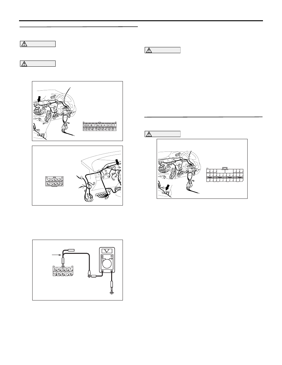
STEP 15. Voltage measurement at the C-37
jumper connector.
CAUTION
A digital multimeter should be used. For details
refer to
CAUTION
The test wiring harness should be used. For
details refer to
(1) Disconnect the centre display connector and the
jumper connector, and measure at the jumper
connector (at the centre display side).
(2) Connect the negative battery terminal, and turn
the ignition switch to the ON position.
(3) Voltage between C-37 jumper connector terminal
No.3 and body earth
OK: Less than 1.0 V
(4) Disconnect the negative battery terminal.
CAUTION
Strictly observe the specified wiring harness
repair procedure. For details refer to
Q: Is the check result normal?
YES :
<less than 1.0 V> Follow diagnostic item 20
"Diagnose CAN bus lines thoroughly." Refer
to
.
NO :
<1.0 V or more> Repair the wiring harness
between the jumper connector and the
centre display connector.
STEP 16. Connector check: C-119 SRS-ECU
connector
CAUTION
The strand end of the twist wire should be within
10 cm from the connector. For details refer to
Q: Is the check result normal?
YES :
Go to Step 17 .
NO :
Repair the defective connector.
AC310631AY
Connector: C-07 <RHD>
Harness side
C-07 (B)
AC310628AZ
Connector: C-37 <RHD>
AC312551 AB
Harness side: C-37
Test
harness
AC310631AZ
Connector: C-119 <RHD>
Harness side
C-119 (Y)
48
37
26
42
31
45
34
47
36
46
35
44
33
43
32
25 24
39
28
41
30
40
29
38
27
23
21
22
A
B