Mitsubishi Grandis. Manual - part 391


  Index      Mitsubishi     Mitsubishi Grandis - service repair manual


Search            


Content   ..  389  390  391  392   ..


Mitsubishi Grandis. Manual - part 391


CLUTCH CONTROL

CLUTCH

21A-7

CLUTCH CONTROL

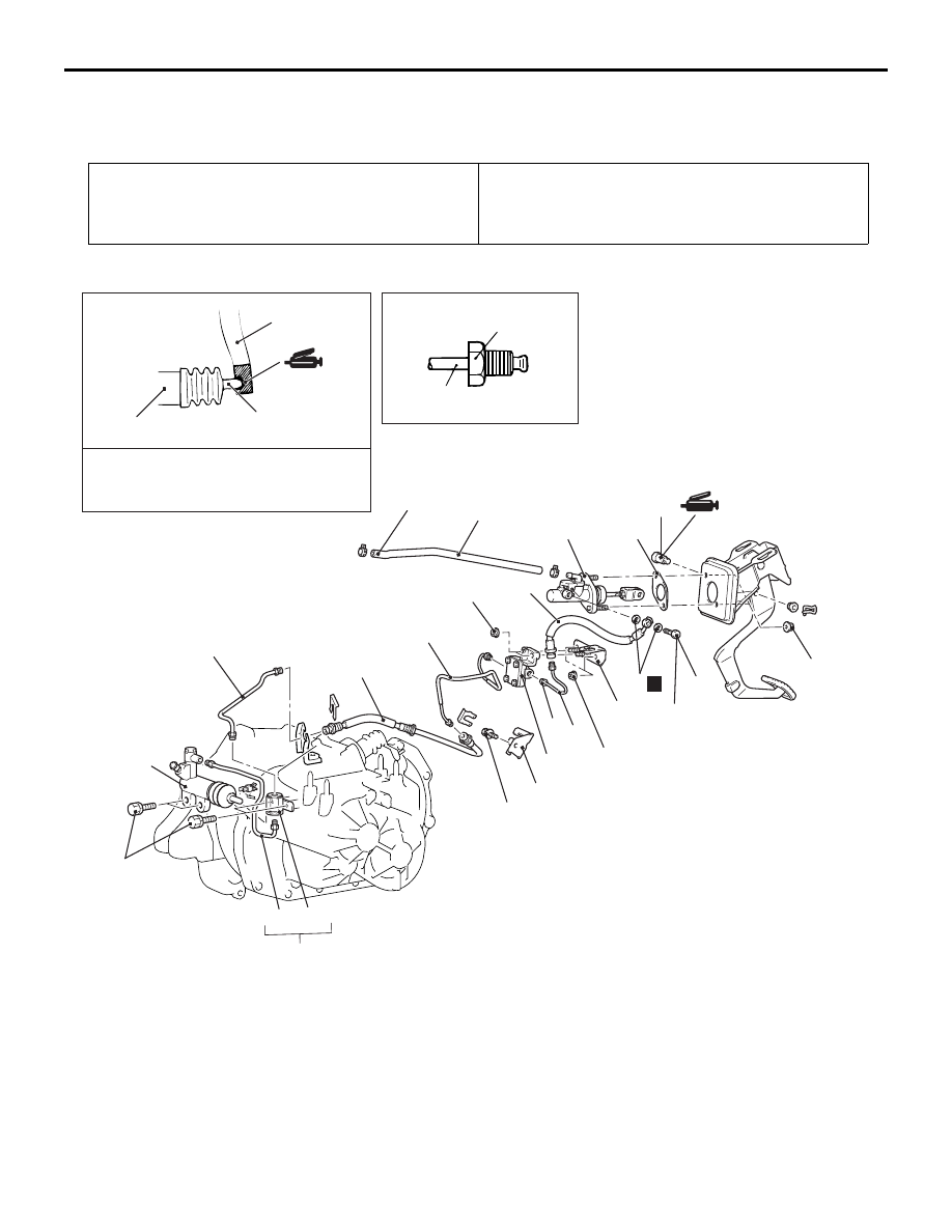
REMOVAL AND INSTALLATION

M1211001900222

<LH drive vehicles>

Pre-removal Operation
• Clutch Fluid Draining

Post-installation Operation
• Clutch Fluid Supplying

• Clutch Line Bleeding (Refer to 

P.21A-3

).

• Clutch Pedal Adjustment (Refer to 

P.21A-2

).

AC311217

12 ± 2 N·m

15 ± 2 N·m

2

11, 15, 17

10

30 ± 4 N·m

12 ± 2 N·m

AB

13

Release fork

Release cylinder
push rod

Specified grease:
MITSUBISHI genuine grease
PART No. 0101011

4

N

16

15

18

11

13

12

18 ± 3 N·m

11

12 ± 2 N·m

12 ± 2 N·m

8

7

1

5

6

14

17

19

9

3

Clutch master cylinder removal 
steps

1.

Reservoir hose and brake fluid 
reservoir connection

2.

Clutch damper bracket

3.

Clutch tube and clutch damper 
assembly connection

Brake master cylinder assembly 
and brake booster (Refer to 
GROUP 35A, Master cylinder 
assembly and brake 
booster

P.35A-14

.)

4.

Clevis pin

5.

Clutch master cylinder

6.

Sealer

>>B<<

7.

Reservoir hose

Clutch master cylinder removal 
steps (Continued)

CLUTCH CONTROL

CLUTCH

21A-8

<R.H. drive vehicles>

8.

Eye bolt

9.

Gasket
Clutch release cylinder removal 
steps

10. Clutch tube and clutch orifice 

assembly

11. Clutch tube
12. Clutch orifice assembly
13. Clutch release cylinder

Clutch line removal steps

>>A<<

14. Clutch hose
15. Clutch tube
16. Clutch damper assembly
17. Clutch tube
18. Clutch hose bracket
19. Clutch hose

Clutch master cylinder removal 
steps (Continued)

AC311218

15 ± 2 N·m

7, 10

9

Release fork

Release cylinder
push rod

Specified grease:
MITSUBISHI genuine grease
PART No. 0101011 or equivalent

AB

12

10

12 ± 2 N·m

4

3

5

1

11

6

7

9

8

18 ± 3 N·m

7

12 ± 2 N·m

2

CLUTCH CONTROL

CLUTCH

21A-9

INSATALLATION SERVICE POINT
>>A<< CLUTCH HOSE INSTALLATION

Install the clutch hose so that the clutch hose plate 
will  touch the master cylinder salience.

>>B<< RESERVOIR HOSE INSTALLATION

Install the reservoir hose with the marking as shown 
in the illustration.

INSPECTION

M1211002000158

• Check the master cylinder or clutch hose for fluid 

leakage.

• Check the clutch hose or tube for cracks or 

clogging.

Clutch master cylinder removal 
steps

1.

Clevis pin

2.

Clutch tube connection

>>B<<

3.

Reservoir hose

4.

Clutch master cylinder

5.

Sealer
Clutch release cylinder removal 
steps

6.

Clutch tube and clutch orifice 
assembly

7.

Clutch tube

8.

Clutch orifice assembly

9.

Clutch release cylinder
Clutch line removal steps

10. Clutch tube
11. Clutch hose bracket
12. Clutch hose

AC310972 AB

Master cylinder 
salience

Clutch hose plate

AC310973

AB

Reservoir
hose

Marking

Marking

<LH drive vehicles>

AC310974 AB

Reservoir
hose

Marking

Marking

<RH drive vehicles>

CLUTCH CONTROL

CLUTCH

21A-10

DISASSEMBLY AND REASSEMBLY

M1211002100229

CLUTCH MASTER CYLINDER

CAUTION

Do not disassemble the piston assembly.

REASSEMBLY SERVICE POINT
>>A<< PUSHROD ASSEMBLY 
INSTALLATION

AC310984

12 ± 2 N·m

N

1

2

3

4

5

8

N

N

2

3

4

1

2

4

2

Piston repair kit

Clutch fluid:
Brake fluid DOT3 OR DOT4

Grease: Rubber grease

AB

6

7

6

7

5

9

N

10

<LH drive vehicles>

<RH drive vehicles>

8

Disassembly steps

1.

Piston stopper ring

2.

Piston assembly

>>A<<

3.

Pushrod assembly

4.

Boot

5.

Spring pin

6.

Nipple

7.

Seal

8.

Master cylinder body

9.

Gasket

10. Damper assembly

AC001144

112.8 ± 0.5 mm

AH


Content   ..  389  390  391  392   ..