Mitsubishi Grandis. Manual - part 390


  Index      Mitsubishi     Mitsubishi Grandis - service repair manual


Search            


Content   ..  388  389  390  391   ..


Mitsubishi Grandis. Manual - part 390


ON-VEHICLE SERVICE

CLUTCH

21A-3

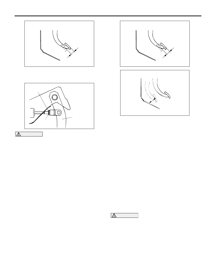
3. Measure the clutch pedal clevis pin play.

Standard value (B): 1 

 3 mm

CAUTION

Do not push in the master cylinder pushrod at 
this time, otherwise the clutch will not operate 
properly.
4. If the clutch pedal height and clutch pedal clevis 

pin play are not within the standard value, loosen 
the setting nut to adjust the clutch pedal height 
and clevis pin play to the standard value.

5. After completing the adjustments, confirm that the 

clutch pedal free play (measured at the face of the 
pedal pad) and the distance between the clutch 
pedal (the face of the pedal pad) and the clutch 
pedal stopper when the clutch is disengaged are 
within the standard value ranges.
Standard value (C): 4 

 13 mm

Standard value (D): 30 mm or more

6. If the clutch pedal free play and the distance 

between the clutch pedal and the clutch pedal 
stopper or toeboard when the clutch is 
disengaged do not agree with the standard 
values, it is probably the result of either air in the 
hydraulic system or a faulty master cylinder, 
release cylinder or clutch. Bleed the air, or 
disassemble and inspect the master cylinder, 
release cylinder or clutch.

CLUTCH BLEEDING

M1211001400205

CAUTION

Use the specified brake fluid. Do not mix brake 
fluids.

Specified fluid: Brake fluid DOT 3 or DOT 4

AC100355 AB

B

Clutch pedal clevis pin play

AC100356

Setting nut

Clutch pedal

12 ± 2 N·m

AD

AC100355 AC

C

Clutch pedal free play

AC312891AB

D

ON-VEHICLE SERVICE

CLUTCH

21A-4

1. Connect a hose with a bottle to the bleeder screw.
2. Open the bleed nipple.
3. Depress the clutch pedal slowly. Open the bleeder 

screw to let air and brake fluid out. Close the 
bleeder screw. Release the clutch pedal. Repeat 
until only brake fluid and no air comes out.

4. Check that the brake fluid reservoir level stays 

between "MAX" and "MIN" marks throughout the 
clutch bleeding process.

CLUTCH SWITCH CHECK AND 
ADJUSTMENT

M1211001100196

1. Adjust the clutch pedal.

2. Connect an ohmmeter to the clutch switch 

connector, and then check for continuity when the 
clutch pedal is fully depressed and when it is 
released outward.

3. If the continuity is incorrect, replace the clutch 

switch.

AC310878 AB

Tester 
connection

Pedal position Specified 

condition

1-2

Fully depressed Less than 2 

Released

Open circuit

1

2

AC310877

CLUTCH PEDAL

CLUTCH

21A-5

CLUTCH PEDAL

REMOVAL AND INSTALLATION

M1211001600221

Post-installation Operation
• Clutch Pedal Adjustment (Refer to 

P.21A-2

).

AC311081

4

7

1

6

2

3

10

9

8

12 ± 2 N·m

12 ± 2 N·m

12 ± 2 N·m

5

4

7

6

1

2

3

8

9

10

12 ± 2 N·m

12 ± 2 N·m

<LH drive vehicles>

<RH drive vehicles>

AB

5

12 ± 2 N·m

Removal steps

Instrument panel under cover 
(Refer to GROUP 52A, Instrument 
panel 

P.52A-2

).

1.

Stopper

2.

Snap pin

3.

Clevis pin

4.

Clutch master cylinder mounting 
nut

5.

Clutch pedal assembly mounting 
bolt

>>A<<

6.

Clutch switch

7.

Nut

8.

Pedal pad

9.

Pedal stopper

10. Clutch pedal assembly

Removal steps (Continued)

CLUTCH PEDAL

CLUTCH

21A-6

INSTALLATION SERVICE POINT
>>A<< CLUTCH SWITCH INSTALLATION

Install the clutch switch at the specified dimension 
when the clutch pedal is released.

AC309757

AB

Clutch pedal

Clutch switch

0.5 – 1.5 mm


Content   ..  388  389  390  391   ..