Mitsubishi Grandis. Manual - part 381
CENTRE DISPLAY
CHASSIS ELECTRICAL
54A-143
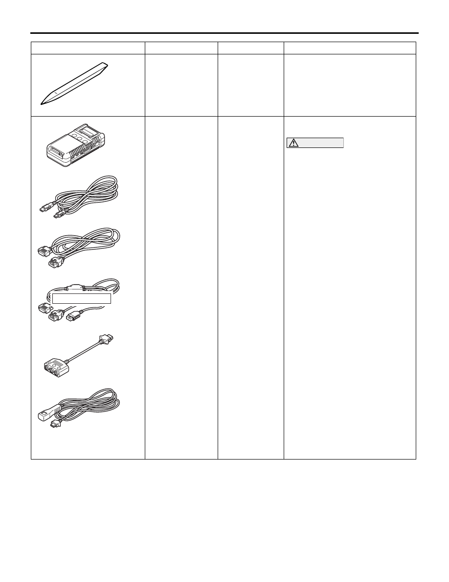
Tool
Number
Name
Application
MB990784
Ornament
remover
Removal of selector lever panel,
instrument centre panel
MB991955
A: MB991824
B: MB991827
C: MB991910
D: MB991911
E: MB991825
F: MB991826
MUT-III
sub-assembly
A: (V.C.I.)
Vehicle
communicatio
n interface
B: MUT-III USB
cable
C: MUT-III Main
harness A
(Vehicles with
CAN
communicatio
n system)
D: MUT-III Main
harness B
(Vehicles
without CAN
communicatio
n system)
E: MUT-III
Measurement
adapter
F: MUT-III
Trigger
harness
Centre display check (diagnosis
code)
CAUTION
For vehicles with CAN
communication, use MUT-III main
harness A to send simulated
vehicle speed. If you connect
MUT-III main harness B instead,
the CAN communication does
not function correctly.
MB990784
MB991910
MB991826
MB991955
MB991911
MB991824
MB991827
MB991825
A
B
C
D
E
F
DO NOT USED