Mitsubishi Grandis. Manual - part 359
COMBINATION METER
CHASSIS ELECTRICAL
54A-55
INSPECTION PROCEDURE 2: Power Supply Circuit. INSPECTION PROCEDURE 3: Odometer and Trip
meter are not displayed. INSPECTION PROCEDURE 4: All the needle meters do not work.
INSPECTION PROCEDURE 5: When the ignition switch turned to the ON position, the indicator and
warning lamps do not illuminate.
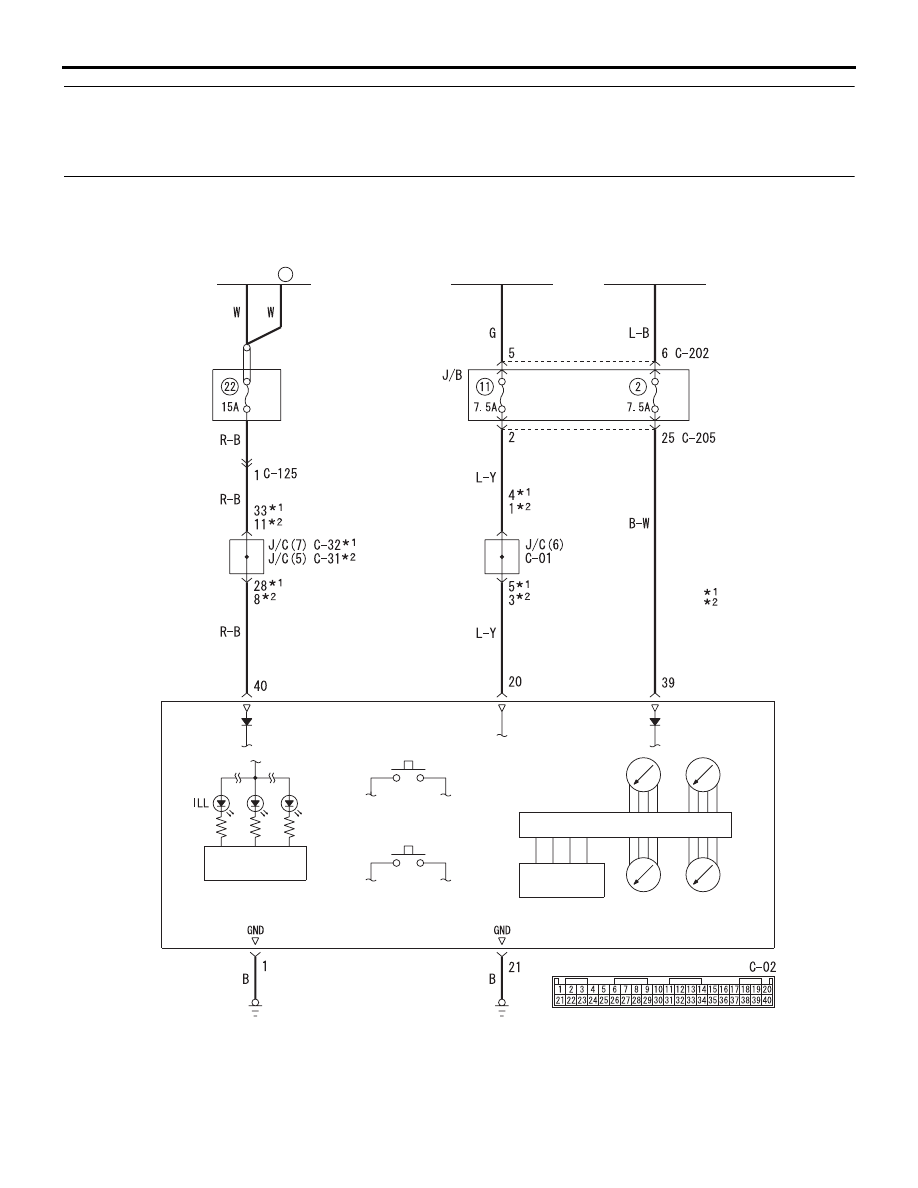
COMMENTS ON TROUBLE SYMPTOM
If the odometer and trip meter are not displayed or all
meter needles don't move, power supply and earth
system to the combination meter, or the combination
meter itself may be defective.
Wire colour code
B : Black LG : Light green G : Green L : Blue W : White Y : Yellow SB : Sky blue
BR : Brown O : Orange GR : Gray R : Red P : Pink V : Violet
Combination Meter Power Supply Circuit
COMBINATION METER
CPU
LCD
ODO/TRIP
FET FOR
DIPPER
DAYTIME
DIPPER BUTTON
TRIPMETER
RESET BUTTTON
IGNITION
SWITCH (ACC)
IGNITION
SWITCH (LG1)
TACHO
F/GA
T/GA
SPEED
:LHD
:RHD
NOTE
FUSIBLE
LINK
26
RELAY
BOX
AC313639